Radiator for LED device

A technology of LED lamps and cooling devices, which is applied in cooling/heating devices of lighting devices, lighting devices, lighting and heating equipment, etc., and can solve problems such as poor heat transfer effect, high processing accuracy and installation requirements, and large volume of cooling devices , to achieve the effect of convenient processing, easy industrialization and safe operation

Inactive Publication Date: 2015-05-13
INST OF ENGINEERING THERMOPHYSICS - CHINESE ACAD OF SCI +1
View PDF6 Cites 5 Cited by
  • Summary
  • Abstract
  • Description
  • Claims
  • Application Information

AI Technical Summary

Problems solved by technology

Although these methods can solve the heat dissipation problem of high-power devices to a certain extent, there are still the following disadvantages: (1) fan + heat sink, in order to enhance the heat dissipation capacity of the heat dissipation device, only by increasing the area of ​​the heat dissipation fins and Increase the fan speed, resulting in loud noise, large and heavy cooling device, which is not conducive to installation and will generate great pressure on electronic devices; (2) fan + heat pipe + radiator, although it can solve the shortcomings in method 1 , but it will increase the complexity of the mechanism itself, the design and installation of heat pipes are often limited by the actual structure, and under the action of limited heat pipes, its heat dissipation capacity is still limited; 3) Liquid cooling technology surpasses the above two in terms of performance This way, and the potential of liquid cooling heat dissipation technology is very high. If a small liquid cooling heat dissipation device is optimized in performance, it can already dissipate 1kW of heat under the premise of controlling noise (the overall thermal resistance of the liquid cooling radiator can be as low as below 0.12℃ / W)
[0006] Since the shape of an ordinary electronic chip is basically a square (cube or cuboid), the cylindrical evaporator is not conducive to contact with the flat surface of the chip due to the diameter of the cylinder, and the heat transfer effect is poor.
The heat dissipation performance of the loop heat pipe of the flat plate evaporator made by micro-processing technology has not yet reached the requirements of commercial use.
However, the existing disc-shaped plate form is complicated due to the manufacturing process of the evaporator, and additional space will be taken up during installation.
Among them, the split plate structure with the bottom plate and the cover structure not only requires high processing accuracy and installation, but also is prone to problems with air tightness.

Method used


Image

  • Radiator for LED device
  • Radiator for LED device
  • Radiator for LED device

Examples


Embodiment Construction

[0048] The present invention will be described in detail below in conjunction with the accompanying drawings. The description in this part is only exemplary and explanatory, and should not have any limiting effect on the protection scope of the present invention. In addition, those skilled in the art can make corresponding combinations of features in the embodiments in this document and in different embodiments according to the descriptions in this document.

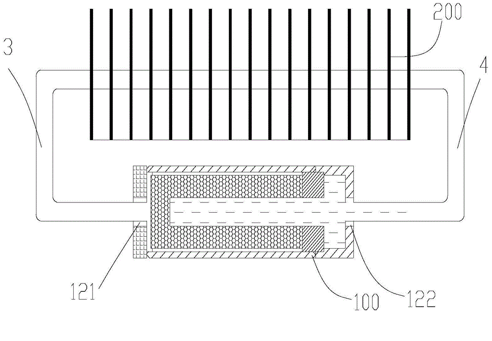
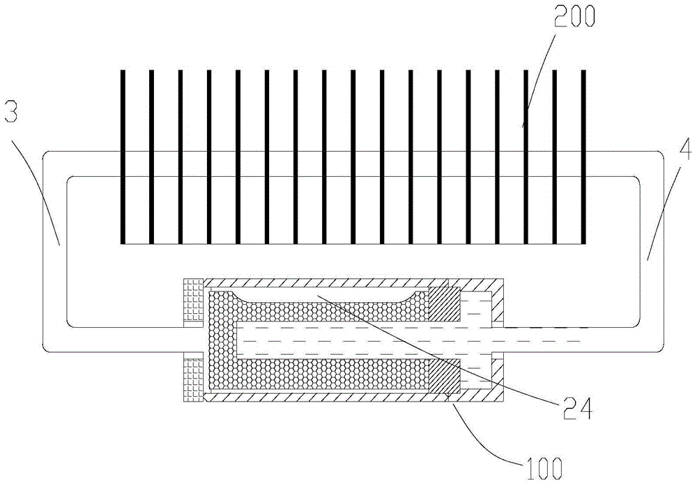
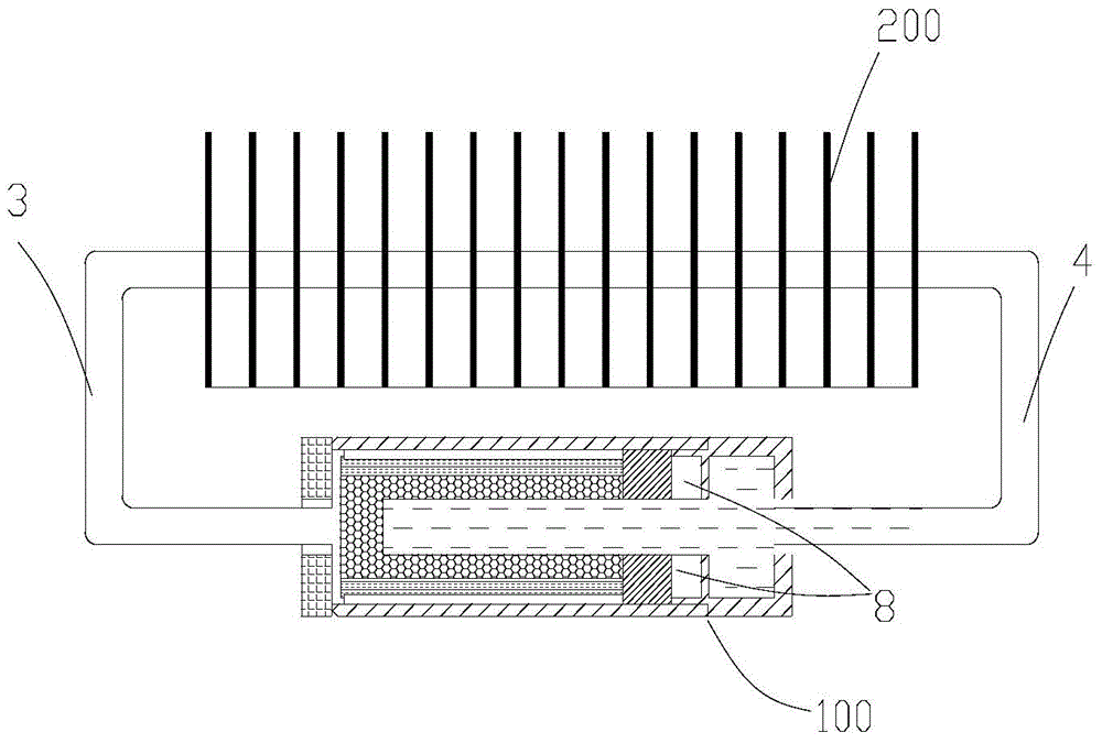
[0049] See Figure 1 to Figure 14 , where as figure 1 , figure 2 and image 3 As shown, there are several different structural diagrams of the heat dissipation device of the LED lamp involved in this embodiment. Especially in the heat dissipation of concentrated light source LED lighting, because the problem of heat dissipation or thermal control of concentrated light source is particularly important and prominent. The heat dissipation device includes an evaporator 100, a steam pipeline 3, a liquid pipeline 4 and a...


PUM


Abstract

The invention relates to a radiator for an LED device. The radiator comprises an evaporator, a steam pipeline, a liquid pipeline and a condenser, wherein the evaporator is provided with a steam outflow port and a liquid inflow port; the steam pipeline and the liquid pipeline are respectively connected with the condenser by the steam outflow port and the liquid inflow port to form a closed heat dissipation loop; the evaporator comprises a heat removal body and a liquid suction core; the heat removal body is provided with an accommodating space; the accommodating space is used for arranging the liquid suction core; the heat removal body is square; the cross section of the accommodating space is circular or oval. The heat removal body is square, and thus, the heat removal body can be tightly attached to a square body of a common electronic chip so as to realize real matching. Meanwhile, the cross section of the accommodating space of the heat removal body adopts circular or oval, and thus, the cross section can realize sealing between the liquid suction core and the heat removal body easily. The radiator for the LED device can really realize safety operation under the high heat flux density.

Description

technical field [0001] The invention belongs to the technical field of heat dissipation of electronic products, in particular to the heat dissipation of concentrated light source LED lighting, in particular to a heat dissipation device for LED lamps. Background technique [0002] The cooling of high-power electronic chips is a very important technical link in electronics, computers, communications and optoelectronic equipment. At present, the commonly used methods for heat dissipation of high-power electronic devices in the market include the following: (1) fan + radiator; (2) fan + heat pipe + radiator; (3) fan + liquid cooling technology. Although these methods can solve the heat dissipation problem of high-power devices to a certain extent, there are still the following disadvantages: (1) fan + heat sink, in order to enhance the heat dissipation capacity of the heat dissipation device, only by increasing the area of ​​the heat dissipation fins and Increase the fan speed,...

Claims


Application Information

Patent Timeline
Patent Type & Authority Applications(China)
IPC IPC(8): F21V29/51F21Y101/02
CPCF21Y2101/00
Inventor 袁达忠唐大伟王念新崔成尹波王念忠粟海滨赵先刚
Owner INST OF ENGINEERING THERMOPHYSICS - CHINESE ACAD OF SCI
Why Eureka
Try Eureka