Micro electro mechanical system (MEMS) centrifugal safety mechanism for rotating ammunition and safety method thereof

A technology for centrifugal insurance and ammunition, applied in weapon accessories, fuzes, offensive equipment, etc., can solve the problems of large occupied space, limit the miniaturization of security devices, and cumbersome assembly links, so as to facilitate modularization, reduce assembly links, and ensure safety. Effect

Inactive Publication Date: 2015-05-13
BEIJING INSTITUTE OF TECHNOLOGYGY
View PDF7 Cites 33 Cited by
  • Summary
  • Abstract
  • Description
  • Claims
  • Application Information

AI Technical Summary

Problems solved by technology

The traditional centrifugal safety mechanism mainly includes compressed cylindrical springs and centrifugal blocks. The as

Method used


Image

  • Micro electro mechanical system (MEMS) centrifugal safety mechanism for rotating ammunition and safety method thereof
  • Micro electro mechanical system (MEMS) centrifugal safety mechanism for rotating ammunition and safety method thereof
  • Micro electro mechanical system (MEMS) centrifugal safety mechanism for rotating ammunition and safety method thereof

Examples


Embodiment 1

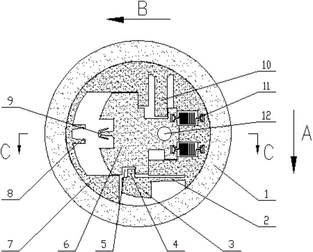
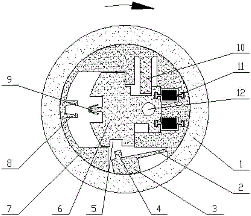
[0032] As shown in Figure 1, in this embodiment, the security device includes a slider 6, a base plate 7, a deck 8, a chuck 9, a locking baffle 10, a spring 11 and a blast hole 12 inside the fuze body 1; , the substrate 7 is arranged on the inner surface of the fuze body 1, and one end of the substrate 7 is equipped with a spring 11, which adopts a MEMS spring, and the other is provided with a deck 8; one end of the slider is connected to the substrate by a spring, and the other end of the slider is connected to the deck The corresponding position is provided with a chuck; the top of the slider is provided with a top groove, and the locking baffle arranged on the top of the substrate is embedded into the top of the slider through the baffle groove; and a blast hole is provided on the slider. In the service processing state, the blast hole is isolated from the blast channel, as shown in Figure 1(b).

[0033] As shown in Figure 1(b), the security device in the fuze is located be...

Embodiment 2

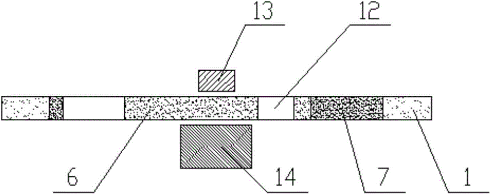
[0037] In the first embodiment, the shape of the centrifugal baffle plate 4 is rectangular, and the groove 5 at the bottom of the slider is correspondingly also rectangular. In this example, if Figure 4 As shown, the top side of the centrifugal baffle 4 has a protrusion, the bottom groove 5 and the centrifugal baffle are complementary figures, and the side also has a protrusion correspondingly, so as to better ensure the restraint performance of the centrifugal safety mechanism on the slider 6 .


PUM


Abstract

The invention discloses a micro electro mechanical system (MEMS) centrifugal safety mechanism for rotating ammunition and a safety method of the MEMS centrifugal safety mechanism. An elastic beam processed on a base plate integrally is connected with a centrifugal mass block, a centrifugal baffle plate fixedly connected on the centrifugal mass block is embedded into a groove in the bottom of a sliding block for restraining the sliding block, when the rotating ammunition falls off accidentally or rolls during order dealing, the elastic beam can ensure that the centrifugal mass block and the centrifugal baffle plate fixedly connected with the centrifugal mass block are at initial position, the centrifugal baffle plate can restrain the sliding block, an explosion propagation hole is isolated from an explosion propagation channel and a safety device is safe; if the launching operation is abnormal, the elastic beam still can drive the centrifugal baffle plate fixedly connected with the centrifugal mass block to return to the initial position to restrain the sliding block, so that the safety of the ammunition after misfiring accidentally is ensured. The MEMS centrifugal safety mechanism is wide in applicability, is suitable for various MEMS safety devices for rotating ammunition, and is integrally processed with the base plate, so that the assembling links are reduced; and the MEMS centrifugal safety mechanism is convenient for modular and generalized design, and is easy for batch production and low in cost.

Description

technical field [0001] The invention relates to the technology of rotating ammunition, in particular to an assembly-free flat MEMS centrifugal insurance mechanism and an insurance method for rotating ammunition. Background technique [0002] The ammunition includes a fuze and a warhead; wherein, the warhead is provided with detonating explosives; the fuze includes a safety device, a detonation control circuit and pyrotechnics, and the safety device ensures that the ammunition is in the process of service processing (assembly, handling, transportation, storage and loading) and It does not detonate before reaching the remote solution distance. After approaching the target or hitting the target, the detonation control circuit controls the detonation of the pyrotechnics to detonate the detonating explosives in the warhead. In recent years, with the influx of new technologies and the continuous expansion of new battlefield environments, the requirements for fuzes have also been c...

Claims


Application Information

Patent Timeline
IPC IPC(8): F42C15/22
Inventor 王辅辅娄文忠王大奎金鑫丁旭冉
Owner BEIJING INSTITUTE OF TECHNOLOGYGY
Why Eureka
Try Eureka