Method for identifying failure state of rotor vibration signal of aircraft engine

A technology for aircraft engine and signal failure, applied in the testing of mechanical components, testing of machine/structural components, measuring devices, etc.

Active Publication Date: 2015-05-13
NORTHWESTERN POLYTECHNICAL UNIV
View PDF14 Cites 20 Cited by
  • Summary
  • Abstract
  • Description
  • Claims
  • Application Information

AI Technical Summary

Problems solved by technology

[0006] In order to solve the problem of selecting key features in the fault characteristics in the existing aircraft engine rotor vibration...

Method used


Image

  • Method for identifying failure state of rotor vibration signal of aircraft engine
  • Method for identifying failure state of rotor vibration signal of aircraft engine
  • Method for identifying failure state of rotor vibration signal of aircraft engine

Examples


Embodiment Construction

[0035] Below in conjunction with accompanying drawing, content of the present invention is described in further detail:

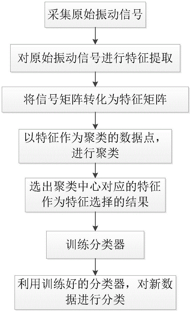
[0036] General faults of aircraft engine rotors include: inner ring faults, outer ring faults, rolling element faults, unbalance faults. The method for identifying the fault state of the aircraft engine rotor vibration signal can identify these fault states, and the general process can be divided into two processes: offline and online: the offline process, that is, the engine rotor vibration data of the known fault category, through the method mentioned in the present invention Processing to obtain a trained classifier; online process, that is, to use the acceleration sensor on the aircraft to collect new vibration data from the engine rotor, and then use the method of vibration signal fault analysis to process the data and substitute it into the trained classifier, and finally Displays fault status results.

[0037] The method for identifying the fault st...


PUM


Abstract

The invention provides a method for identifying the failure state of the rotor vibration signal of an aircraft engine. The method mainly includes the following steps of: firstly extracting 11 time domains and frequency domains and characteristics of time and frequency domains of the rotor vibration signal; selecting the proper characteristics by clustering; training a classifier by using the clustering result; at last introducing new data into the trained classifier to generate classification result. According to the method, the problem that, when in existing aircraft engine rotor failure state identification, the lots of extracted diagnosis characteristics have many uncorrelated or uncorrelated due to objective and subjective reasons is overcome. The method of classifying rotor vibration signal faults of the aircraft engine by using the combination of the clustering method and the classifier is adopted to provides a frame of the method for identifying the failure state of the rotor vibration signal of the aircraft engine, the key characteristic sensitive to the fault characteristic can be automatically identified, the correlated characteristics insensitive to the fault characteristic can be removed, and the performance of identifying the failure state of the rotor vibration signal of the aircraft engine can be effectively promoted.

Description

technical field [0001] The invention belongs to the technical field of fault diagnosis and state monitoring of electromechanical systems, and specifically relates to a method for identifying fault states of aircraft engine rotor vibration signals. Background technique [0002] The aircraft operates in a complex environment and has high requirements for system reliability. The status monitoring, diagnosis and prediction of the aircraft system are important means to ensure the safety of the aircraft. For example, aircraft systems need to monitor engine performance (such as patent: CN 103370667A), landing gear status (such as patent: CN 103963986), elevator control (such as patent: CN 202987498), and various electronic and electromechanical devices (such as patent: CN 102700718A) The status of each system such as whether it is working normally. The overall state of these systems is affected by the sub-systems, for example, the state monitoring of anti-skid brake control box (s...

Claims


Application Information

Patent Timeline
IPC IPC(8): G01M13/00
Inventor 刘贞报李洋布树辉张超
Owner NORTHWESTERN POLYTECHNICAL UNIV
Why Eureka
Try Eureka