Method, device and system for detecting optical fiber faults

A fiber optic fault and fiber optic fault detection technology, applied in transmission systems, electromagnetic wave transmission systems, electrical components, etc., can solve problems such as low test performance, limited optical power, and limited processing capacity

Active Publication Date: 2014-11-12
CHINA TELECOM CORP LTD
View PDF3 Cites 9 Cited by
  • Summary
  • Abstract
  • Description
  • Claims
  • Application Information

AI Technical Summary

Problems solved by technology

However, due to limited optical power and limited p...

Method used


Image

  • Method, device and system for detecting optical fiber faults
  • Method, device and system for detecting optical fiber faults
  • Method, device and system for detecting optical fiber faults

Examples


Embodiment Construction

[0038] The following will clearly and completely describe the technical solutions in the embodiments of the present invention with reference to the accompanying drawings in the embodiments of the present invention. Obviously, the described embodiments are only some, not all, embodiments of the present invention. The following description of at least one exemplary embodiment is merely illustrative in nature and in no way taken as limiting the invention, its application or uses. Based on the embodiments of the present invention, all other embodiments obtained by persons of ordinary skill in the art without creative efforts fall within the protection scope of the present invention.

[0039] The relative arrangements of components and steps, numerical expressions and numerical values ​​set forth in these embodiments do not limit the scope of the present invention unless specifically stated otherwise.

[0040] At the same time, it should be understood that, for the convenience of d...


PUM


Abstract

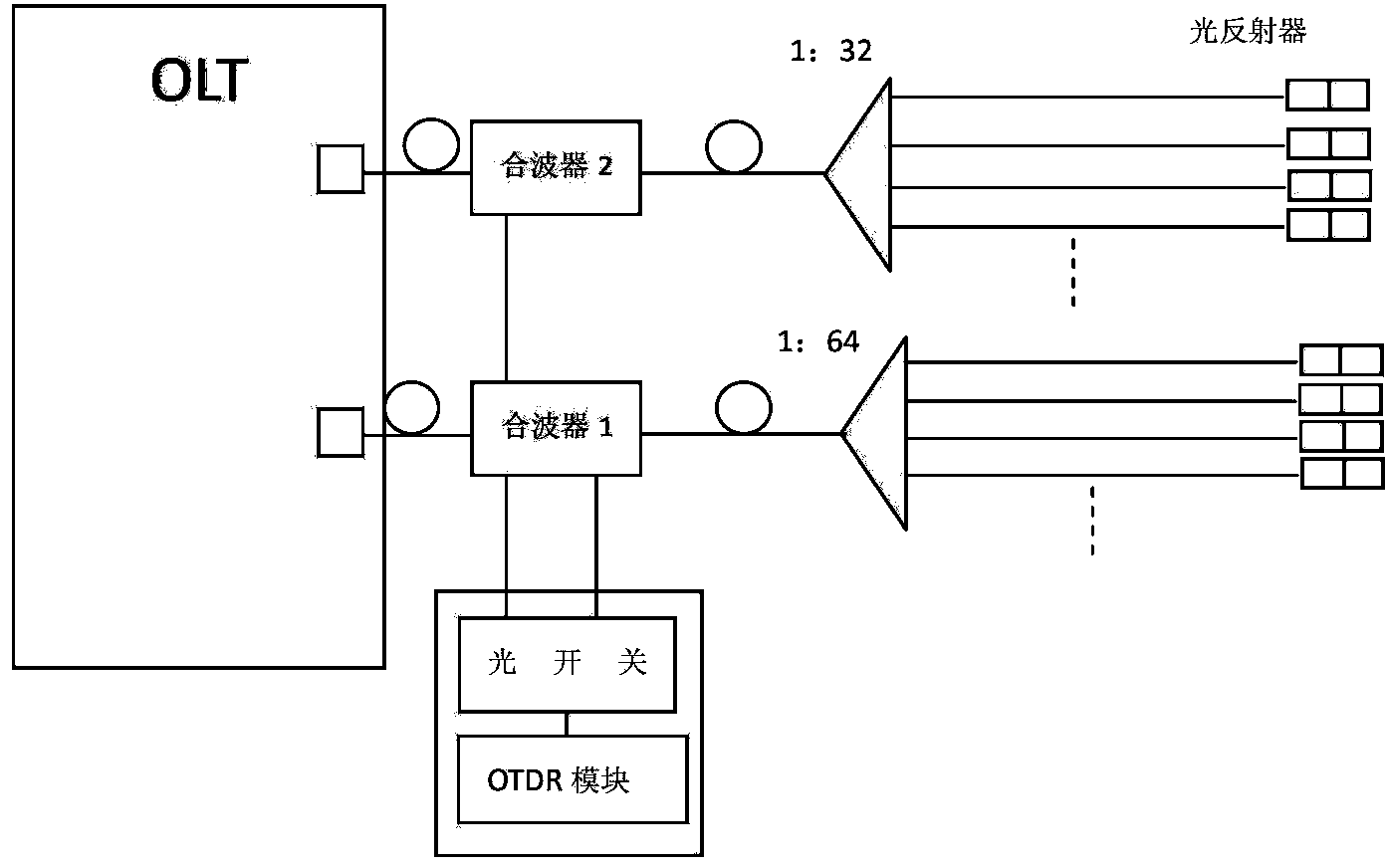
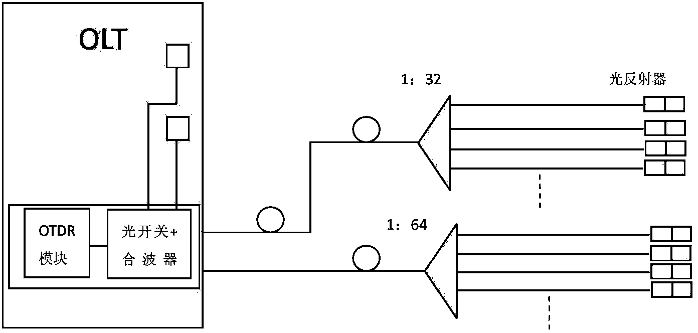
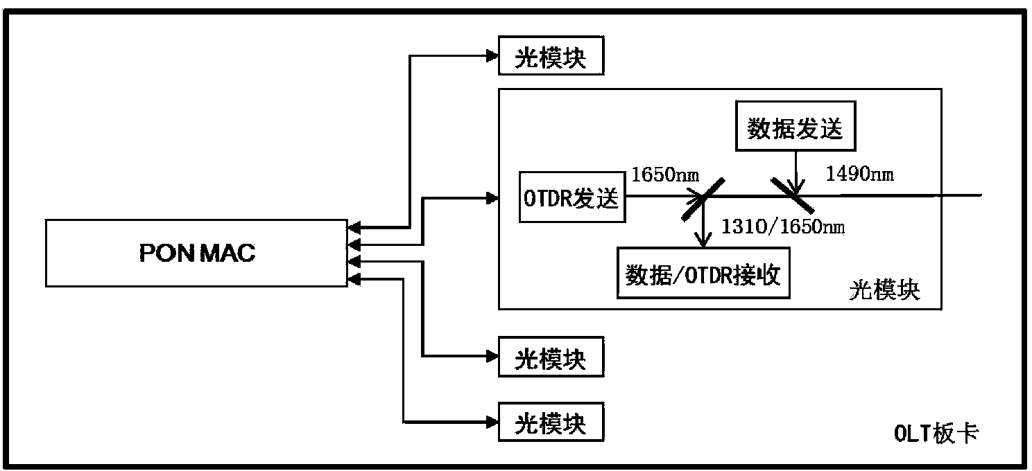
The invention discloses a method, device and system for detecting optical fiber faults. The method for detecting the optical fiber faults includes the steps that after receiving an optical fiber fault detection request transmitted by a network element management system, a PON MAC module transmits starting indication information to an OTDR module, and the switching state of an optical switch module is controlled; after receiving the starting indication information, the OTDR module transmits an OTDR detection signal to the optical switch module; according to control of the PON MAC module, the OTDR detection signal is switched by the optical switch module into corresponding optical fibers, and an OTDR reflected signal is received from the corresponding optical fibers and transmitted to the OTDR module; the OTDR module extracts OTDR sampling data from the OTDR reflected signal, and the OTDR sampling data are transmitted to the network element management system through the PON MAC module. As the OTDR module and the optical switch module are arranged in a PON board card, on the basis that OTDR optical fiber testing performance is guaranteed, the optical fiber diagnosis cost can be reduced, and meanwhile size limitation and power dissipation limitation of an optical module are avoided.

Description

technical field [0001] The invention relates to the field of optical access networks, in particular to a method, device and system for detecting fiber faults. Background technique [0002] Optical fiber diagnosis technology is to comprehensively analyze PON (Passive Optical Network, Passive Optical Network) network management information or OTDR (Optical Time Domain Reflectometer, Optical Time Domain Reflectometer) test information through the test diagnosis server, and remotely locate the optical fiber and optical fiber in the passive optical network. Device performance and faults, so as to realize centralized monitoring and fast fault location of optical fiber networks, reduce unnecessary dispatch orders, save labor costs, and improve operation and maintenance management efficiency. [0003] At present, there are mainly the following implementation methods for PON network OTDR optical fiber testing: [0004] 1) Independent shared OTDR and slot shared OTDR [0005] Indepe...

Claims


Application Information

Patent Timeline
IPC IPC(8): H04B10/075
Inventor 任艳欧月华兰潮彭莉朱晓洁张凝昊毛宇
Owner CHINA TELECOM CORP LTD
Why Eureka
Try Eureka