Oil production simulation system and simulation method

A simulation system and simulation method technology, which is applied to simulators, space navigation condition simulation devices, teaching models, etc., can solve the problems of large floor area, training on site, and high airtightness requirements, and achieve equipment footprint The effect of small area, improved training effect, and high simulation effect

Active Publication Date: 2017-03-15
SOUTHWEST PETROLEUM UNIV +1
View PDF8 Cites 0 Cited by
  • Summary
  • Abstract
  • Description
  • Claims
  • Application Information

AI Technical Summary

Problems solved by technology

However, since almost all drilling sites and facilities are distributed in the wild, it is impossible to carry out training on site. If only relying on conventional classroom teaching or laboratory operations, due to the lack of vivid, intuitive and vivid auxiliary means and methods, it is inevitable to fall into the The embarrassing situation that the course content is simple and boring, and the learning effect of the students is poor, and the training is difficult to achieve the expected effect
[0004] Traditional oil recovery simulation training is conducted using real equipment for training, which uses water as the medium to simulate the flow of crude oil. The traditional simulation training equipment is pressurized equipment, which has potential safety hazards. It is filled with water, and the system maintenance cost is high and easy. Damaged, filled with water, pressure, temperature, viscosity, flow and other data are very different from those on site, unable to reflect on-site working conditions, poor training effect, high airtightness requirements, expensive equipment, and certain requirements on the appearance of the equipment, usually only Standard parts can be used, and it is difficult to simulate accidents such as leakage, blockage, valve damage, and freezing blockage. All equipment must be physically connected, which makes equipment layout difficult and occupies a large area

Method used


Image

  • Oil production simulation system and simulation method
  • Oil production simulation system and simulation method
  • Oil production simulation system and simulation method

Examples


Embodiment Construction

[0039] The technical solution of the present invention will be further described in detail below in conjunction with the accompanying drawings, but the protection scope of the present invention is not limited to the following description.

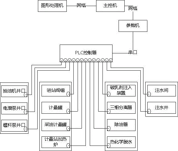
[0040] Such as figure 1 As shown, the oil production simulation system includes an oil production simulation device, a PLC controller and a control unit. The control unit includes a main control machine, a parameter machine and a graphics processor. The oil production simulation device is connected with the PLC controller, and the PLC controller communicates with the parameter The parameter computer and the graphics processor are respectively connected to the main control computer through the communication network;

[0041] The described oil production simulation device is provided with valves, display meters, switches, etc., and the PLC controller is provided with a collector for circularly collecting the valve opening and switch state on ...


PUM


Abstract

The invention discloses an oil production simulation system and a simulation method. The oil production simulation system comprises an oil production simulation device, a PLC (programmable logic controller) controller and a control unit; the control unit comprises a main control computer, a parameter machine and a picture processor; the oil production device is connected with the PLC controller, and the PLC controller is connected with the parameter machine through a serial port; the parameter machine and the picture processor are respectively connected with the main control computer through a communication network; the oil production simulation method includes PLC data collection, calculation of the main control computer and virtual presentation. According to the oil production simulation system and the simulation method provided by the invention, the shortcoming that the pipe network flowing condition is hard to calculate in real time by a traditional calculation method can be solved, pressure and flowing conditions of the pipe network can be calculated in real time, and simulation of leakage, blockage and super-pressure accident can be conveniently carried out; moreover, the floor area of the device is small, every student can intuitionally observe the response action of every gas production simulation device and really reach a highly simulation effect; thus the training scene feeling is enhanced and the training effect is improved.

Description

technical field [0001] The invention relates to the field of oil drilling simulation, in particular to an oil recovery simulation system and a simulation method. Background technique [0002] Oil production engineering is a general term for various engineering and technical measures taken to the reservoir through production wells and injection wells according to the development objectives in the process of oilfield production. The task of oil production engineering is to make oil and gas flow into wells smoothly through a series of engineering and technical measures that can act on oil reservoirs, and the wells can efficiently lift them to the ground for separation and metering; its goal is to economically and effectively improve oil and gas. Crude Oil Recovery. [0003] However, for new oilfield employees or petroleum-related majors, they have no perceptual knowledge of oil production processes, equipment such as metering tanks, heating furnaces, or handling methods in cas...

Claims


Application Information

Patent Timeline
Patent Type & Authority Patents(China)
IPC IPC(8): G09B9/00G09B25/02
CPCG09B9/00G09B25/02
Inventor 张鉴益龚捷
Owner SOUTHWEST PETROLEUM UNIV
Why Eureka
Try Eureka