Novel rib unfolding mechanism of high precision umbrella type antenna

An umbrella-shaped antenna and deployment mechanism technology, which is applied in the directions of folding antennas, antenna supports/installation devices, mechanical equipment, etc., can solve the problem that the function and performance requirements of the rib deployment mechanism have not been found, and the mouth-forward state deployment test cannot be performed. Can not be folded in reverse and other problems, to achieve the effect of adapting to the space environment, high repeatability and reducing friction loss

Active Publication Date: 2015-05-13
XIAN INSTITUE OF SPACE RADIO TECH
View PDF3 Cites 27 Cited by
  • Summary
  • Abstract
  • Description
  • Claims
  • Application Information

AI Technical Summary

Problems solved by technology

[0010] According to the latest information, there are currently two specific structural forms for the deployment of high-precision umbrella-shaped deployable antennas: one is the umbrella-shaped deployable antenna developed by Russia and applied to the relay satellite "Ray 5". The deployment is driven by steel wire pulling, that is, each rib is pulled and unfolded by a steel wire. Since the steel wire can only transmit pulling force but not thrust, the antenna cannot stop after the unfolding process begins, let alone achieve reverse folding through the unfolding mechanism. , and when the antenna mouth faces forward, the lower half of t

Method used


Image

  • Novel rib unfolding mechanism of high precision umbrella type antenna
  • Novel rib unfolding mechanism of high precision umbrella type antenna
  • Novel rib unfolding mechanism of high precision umbrella type antenna

Examples


Embodiment Construction

[0026] The following describes the implementation process of the present invention in detail with reference to the drawings and specific examples.

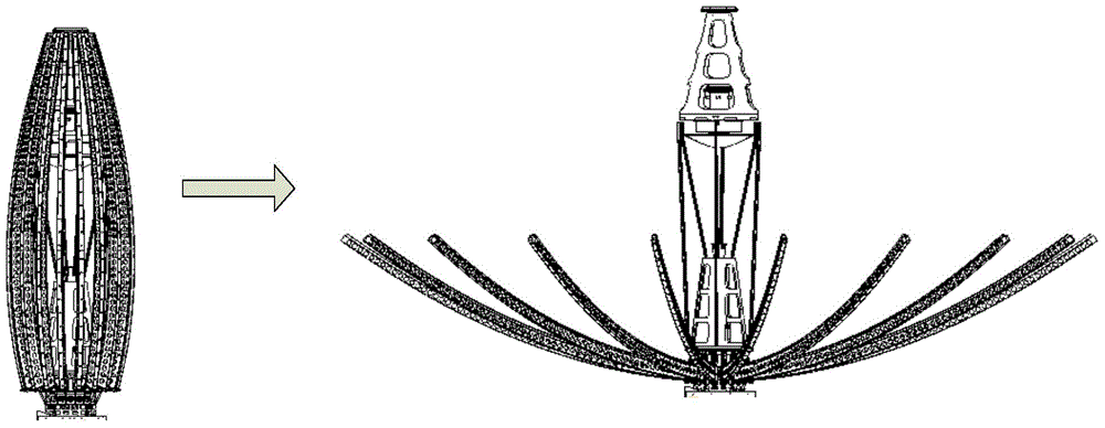
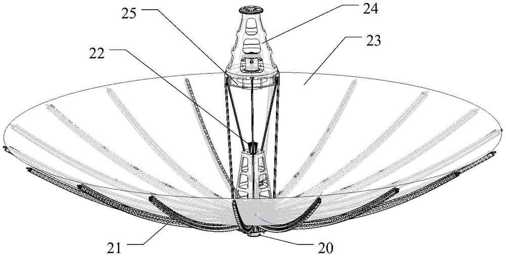
[0027] Such as figure 2 As shown, the radially ribbed umbrella-shaped deployable antenna is mainly composed of the present invention, the radial rib 21, the feed assembly 22, the mesh main reflector 23, the supporting truss 24, the sub reflector 25 and so on. The present invention is the installation basis of the umbrella antenna. The feed source 22 and the sub-reflector 25 are installed on the supporting truss 24, and the supporting truss 24 is installed on the upper end surface of the present invention. The antenna rib 21 is the skeleton of the entire mesh main reflector 23 The structure is used to install a fixed tension cable net and a metal net. The antenna ribs 21 are uniformly distributed and installed on the H surface of the present invention in the circumferential direction. The antenna ribs 21 are driven from the collapsed ...


PUM


Abstract

Provided is a novel rib unfolding mechanism of high precision umbrella type antenna; a motor and a speed reducer provide power for the rib unfolding mechanism; a lead screw is connected with the speed reducer via a shaft coupling block; the lead screw rotates under the drive of the speed reducer; a nut is sleeve on the lead screw in order to transform the rotation movement of the lead screw into the up and down linear movement of the nut; a sliding disk is sleeve on a guiding sleeve; the sliding disk is connected with the nut by a limit screw; and the sliding disk moves up and down along with the nut; one end of a connecting rod is hinged with the sliding disk through a spindle; the other end is hinged with a locking arm; umbrella type antenna ribs are installed on a H surface of the locking arm; the connecting rod drives the locking arm to rotate; the rotation of the locking arm drives the antenna ribs to finish unfolding and folding actions; an in-position locking device is used for locking after the antenna ribs are unfolded in position, thus giving the antenna ribs enough rigidity; the novel rib unfolding mechanism of high precision umbrella type antenna achieves smooth unfolding and folding of the high precise umbrella type antenna; and the process is controllable; the novel rib unfolding mechanism of high precision umbrella type antenna has advantages of high in repeatedly unfolding precision and small in thermal deformation.

Description

Technical field [0001] The invention relates to a novel rib deployment mechanism for a high-precision umbrella antenna, which is used for realizing the deployment and folding of the high-precision umbrella antenna, and belongs to the technical field of satellite antenna mechanisms. Background technique [0002] The invention is derived from the development of a high-precision radial rib umbrella-shaped expandable antenna. In order to meet the envelope requirements of satellite launching, the large-aperture antenna should have the characteristic of high storage ratio. The antenna is locked and stored on the satellite platform during satellite launching. , And then expand into working state after the rail, such as figure 1 As shown, this requires the antenna product to be able to realize the functions of folding and unfolding in addition to the established task functions. [0003] Such as figure 2 As shown, the radial rib umbrella-shaped deployable antenna is mainly composed of a ri...

Claims


Application Information

Patent Timeline
IPC IPC(8): H01Q1/08H01Q1/10H01Q1/22F16H37/12
Inventor 李菡王波王朋朋栗卫华
Owner XIAN INSTITUE OF SPACE RADIO TECH
Why Eureka
Try Eureka