Seal ring

A technology of sealing ring and annular groove, which is applied in the direction of engine sealing, engine components, mechanical equipment, etc., can solve the problem of response characteristic decline, and achieve the effect of suppressing leakage and suppressing sliding wear

Inactive Publication Date: 2015-05-13
NOK CORP
View PDF4 Cites 7 Cited by
  • Summary
  • Abstract
  • Description
  • Claims
  • Application Information

AI Technical Summary

Problems solved by technology

In addition, when the pressure in the high-pressure region (H) is increased, the response characteristics will be degraded

Method used


Image

  • Seal ring
  • Seal ring
  • Seal ring

Examples


Embodiment 1

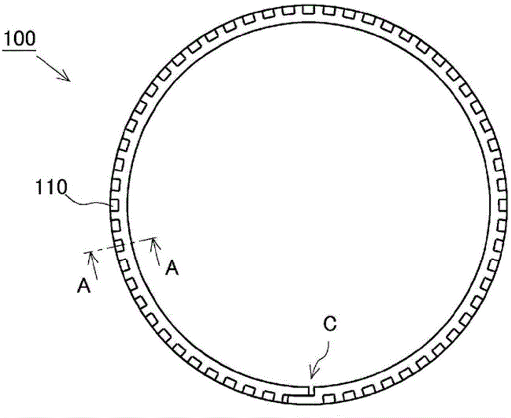
[0074] Below, refer to Figure 1 to Figure 6 The seal ring of Example 1 of the present invention will be described. The sealing ring of this embodiment is installed in an annular groove provided on the outer periphery of the shaft, and is used to seal the annular gap between the shaft and the casing, and separate the high-pressure area and the low-pressure area where the fluid to be sealed is located. In this embodiment, the shaft is rotated relative to the housing. However, the seal ring of the present invention is also applicable to a structure in which the housing rotates with respect to a shaft, and a structure in which both the shaft and the housing rotate relatively.

[0075] (Structure of sealing ring)

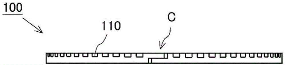
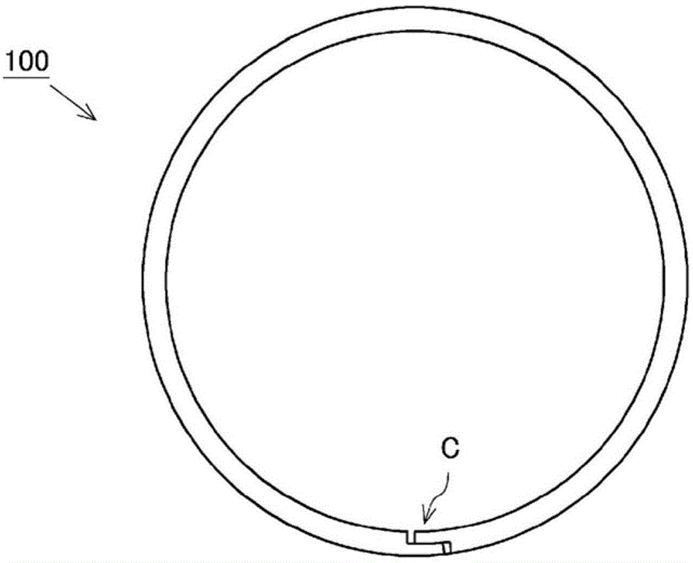
[0076] Figure 1 to Figure 4 It is a figure which shows the structure of the seal ring 100 of this Example. figure 1 , image 3 is a side view of the seal ring 100 . figure 1 Indicates the side facing the low-pressure area side when the seal ring 100 is installe...

Embodiment 2

[0094] Below, refer to Figure 7 , Figure 8 The seal ring of Example 2 of the present invention will be described. The seal ring of this embodiment differs from the seal ring of Embodiment 1 in the groove structure. The description of the same structure and function as in the first embodiment is omitted here.

[0095] (Structure of sealing ring)

[0096] Figure 7 It is a partial side view of the seal ring 100a of this embodiment. Figure 7 The side surface of the seal ring 100a on the low-pressure region (L) side is shown.

[0097] In the seal ring 100a of this embodiment, a plurality of side grooves 110a are provided on the side surface on the low-pressure region (L) side. As in the first embodiment, the side groove 110 a extends from the outer peripheral surface to the inner peripheral surface to a position not reaching the inner peripheral surface. In Embodiment 1, the side groove 110 provided on the side surface of the seal ring 100 extends in the radial direction...

Embodiment 3

[0104] Below, refer to Figure 9 The seal ring according to Example 3 of the present invention will be described. The seal ring of this embodiment differs from the seal ring of Embodiment 1 in the groove structure. The description of the same structure and function as in the first embodiment is omitted here.

[0105] (Structure of sealing ring)

[0106] Figure 9 It is a partial side view of the seal ring 100b of this embodiment. Figure 9 The side surface of the seal ring 100b on the low-pressure region (L) side is shown.

[0107] In this embodiment, the shaft 200 rotates not only in the forward direction but also in the reverse direction relative to the casing 300 . In addition, in the seal ring 100b of this embodiment, a plurality of side grooves 110a, 110b are respectively provided on the side surface on the low-pressure region (L) side. As in the first embodiment, the side grooves 110a and 110b extend from the outer peripheral surface to the inner peripheral surface...


PUM


Abstract

Provided is a seal ring which can reduce the amount of leakage of fluid to be sealed, the leakage flowing from a high-pressure region to a low-pressure region. A seal ring (100) is mounted in an annular groove (210) provided in the outer periphery of a shaft (200). The seal ring (100) seals the annular gap between the shaft (200) and a housing (300), the shaft (200) and the housing (300) rotating relative to each other, and separates a low-pressure region (L) and a high-pressure region (H) in which fluid to be sealed is present. When the shaft (200) and the housing (300) rotate relative to each other, a side surface of the seal ring (100), the side surface facing the low-pressure region, and a side surface of the annular groove slide on each other. The seal ring (100) is provided with a side surface groove (110) which is provided in a side surface of the seal ring (100), the side surface facing the low-pressure region (L), and which extends from the position at which the side surface groove (110) is exposed to the low-pressure region (L), toward the inner peripheral surface side of the seal ring (100) to a position not reaching the inner peripheral surface.

Description

technical field [0001] The invention relates to a sealing ring for sealing an annular gap between a relatively rotating shaft and a housing. Background technique [0002] Sealing rings are known from the prior art for closing the annular gap between a relatively rotating shaft and a housing. Below, refer to Figure 25 A seal ring in an example of the prior art will be described. Figure 25 It is a cross-sectional schematic diagram showing the use state of the seal ring in the conventional example. [0003] The sealing ring 500 is installed in the annular groove 210 provided on the outer periphery of the shaft 200, and is used to seal the annular gap between the relatively rotating shaft 200 and the housing 300, and to separate the high-pressure area (H) from the low-pressure area (L). function. Here, the seal ring 500 is kept in close contact with the side surface of the annular groove 210 on the low-pressure region (L) side and the inner peripheral surface 310 of the shaf...

Claims


Application Information

Patent Timeline
Patent Type & Authority Applications(China)
IPC IPC(8): F16J15/18
CPCF16J15/3272F16J15/441
Inventor 德永涉
Owner NOK CORP
Why Eureka
Try Eureka