Rotating shoe rack

A technology for shoe racks and shoes, which is applied in the direction of hangers, clothing, applications, etc., can solve the problems that the spacing cannot be adjusted at will, poor air permeability of shoes, and large floor space, etc., to achieve small footprint, convenient shoe placement, and good support performance Effect

Inactive Publication Date: 2015-05-20
庞燕
View PDF0 Cites 0 Cited by
  • Summary
  • Abstract
  • Description
  • Claims
  • Application Information

AI Technical Summary

Problems solved by technology

However, there are the following defects: first, the products built into the wall cannot be moved; second, the shoes have poor air permeability; third, the distance between each layer cannot be adjusted at will; fourth, the floor space is large

Method used


Image

  • Rotating shoe rack

Examples


Embodiment Construction

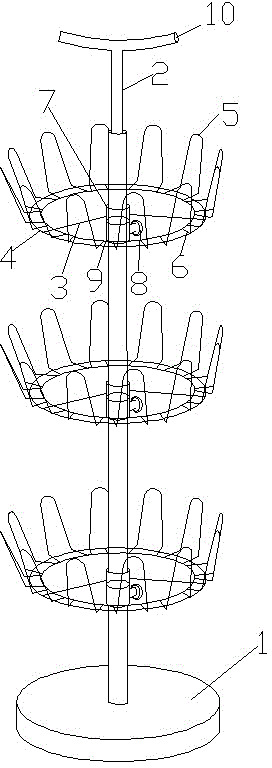
[0017] Such as figure 1 As shown, a rotating shoe rack includes a base 1, a central rod 2 and a shoe placement device, a central rod 2 is installed on the base 1, and a shoe placement device is installed on the central rod 2.

[0018] The shoe placement device includes a horizontal support 3, an annular support 4, a tubular support 7 and a pendant.

[0019] The tubular support 7 is rotatably arranged on the central rod 2, the horizontal support 3 is evenly arranged on the outer peripheral wall of the tubular support 7, the end of the horizontal support 3 is provided with an annular support 4, and the annular support 4 is provided with a pendant.

[0020] The hanger includes an inverted U-shaped hook 5 and a horizontal connecting piece 6 , and the inverted U-shaped hook 5 is arranged on the ring support 4 through the horizontal connecting piece 6 . The two ends of the inverted U-shaped hook 5 are provided with horizontal connectors 6 respectively, and the inverted U-shaped hoo...


PUM


Abstract

The invention discloses a rotating shoe rack which comprises a base, a center rod and shoe placing devices. The center rod is installed on the base and provided with the shoe placing devices. Each shoe placing device comprises horizontal supporting parts, annular supporting parts, a tubular supporting part and hanging parts. The tubular supporting parts are arranged on the center rod in a rotating mode. The horizontal supporting parts are uniformly arranged on the outer peripheral wall of the corresponding tubular supporting part. The annular supporting parts are arranged at the ends of the horizontal supporting parts. The hanging parts are arranged on the annular supporting parts. The hanging parts comprise inverted-U-shaped hooks and horizontal connecting parts. The inverted-U-shaped hooks are arranged on the annular supporting parts through the horizontal supporting parts. The rotating shoe rack can rotate, and is flexible, capable of being moved, small in occupied area, large in bearing force, firm in structure and good in supporting property, and shoes can be taken and placed conveniently.

Description

technical field [0001] The invention relates to a shoe rack, in particular to a rotating shoe rack, which belongs to the technical field of daily necessities. Background technique [0002] Shoe rack is an indispensable product in home life. Some of the existing shoe racks are built into the wall, and some are independent structures. Regardless of the placement method, the basic structure of the shoe rack includes horizontal or inclined support plates for placing shoes, and the number of support plates can be designed according to needs. Adjacent support plates are connected by vertical supports. The shoe rack with this structure has a simple structure and is easy to process and manufacture. However, there are the following defects: first, the products built into the wall cannot be moved; second, the shoes have poor air permeability; third, the distance between each layer cannot be adjusted at will; fourth, the floor space is large. Therefore, need a kind of new shoe rack...

Claims


Application Information

Patent Timeline
Patent Type & Authority Applications(China)
IPC IPC(8): A47G25/80
Inventor 庞燕
Owner 庞燕
Why Eureka
Try Eureka