Tube curvature compensation method and laser cutting device

A compensation method and laser cutting technology, which is applied in laser welding equipment, tubular objects, applications, etc., can solve problems such as increased production costs, damaged cutting heads, and discrepancies in positions, and achieves the effect of improving the pass rate and strong versatility

Active Publication Date: 2015-05-20
HANS LASER TECH IND GRP CO LTD
View PDF8 Cites 7 Cited by
  • Summary
  • Abstract
  • Description
  • Claims
  • Application Information

AI Technical Summary

Problems solved by technology

If the compensation operation is not performed in time, it is easy to cause the cut contour to deviate from the pre-programmed position, resulting in deviation of the center position of the cutting contour, reducing the pass rate of processing and production, and even damaging the cutting head
[0003] In order to solve the above problems, manual and mechanical auxiliary methods

Method used


Image

  • Tube curvature compensation method and laser cutting device
  • Tube curvature compensation method and laser cutting device
  • Tube curvature compensation method and laser cutting device

Examples


Embodiment Construction

[0032] Now in conjunction with the accompanying drawings, the preferred embodiments of the present invention will be described in detail.

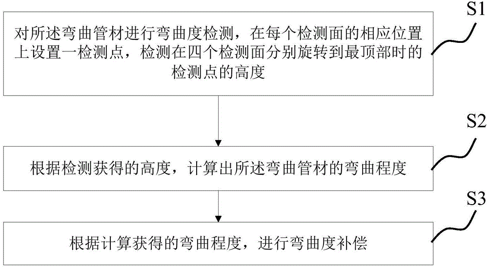
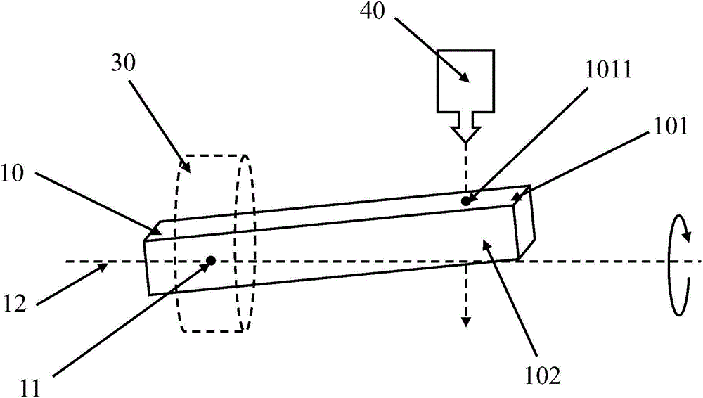
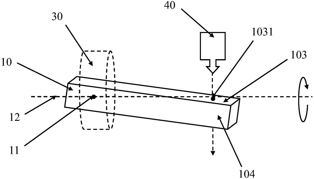
[0033] like Figure 1~5 As shown, a preferred embodiment of the pipe curvature compensation method is provided, wherein figure 1 is the schematic block diagram of the curvature compensation method, figure 2 is the detection indication of the compensation method Figure 1 , image 3 is the detection indication of the compensation method Figure II , Figure 4 is the schematic diagram of the curved pipe structure, Figure 5 is the schematic diagram of the cutting profile of the curved pipe.

[0034] A method for compensating the bending degree of a pipe. Before compensation, the curved pipe 10 is clamped by the clamping member 30, and the curved pipe 10 is rotated around the rotation axis 12. The rotation axis 12 is a horizontal axis passing through the center 11 of the clamping position, and the compensation After the bending operat...


PUM


Abstract

The invention relates to the technical field of tube cutting, in particular to a tube curvature compensation method. A curved tube is clamped before compensation and rotated around a rotating shaft, the rotating shaft is a horizontal shaft passing through the center of a clamping position, and the curved tube comprises four detection surfaces. The method includes the first step of conducting curvature detection on the curved tube, the second step of calculating the curvature of the curved tube according to the height obtained through detection, and the third step of conducting curvature compensation according to the curvature obtained through calculation. The curvature of the curved tube is detected and the position relation of the cutting surface and a cutting head of the curved tube is adjusted according to a detection result, so that the demands for processing production are met, it is guaranteed that cut contour position precision is within a reasonable error range, and the percent of pass of processing production is increased; laser cutting universality is higher, and cost and conditions for selective purchasing, carrying and storing of tubes are reduced.

Description

technical field [0001] The invention relates to the technical field of pipe cutting, in particular to a pipe curvature compensation method and a laser cutting device. Background technique [0002] When cutting and processing curved pipes, especially curved pipes such as square pipes, rectangular pipes and waist round pipes, it is generally necessary to perform curvature compensation operations (that is, to adjust the positional relationship between the cutting surface of the curved pipe and the cutting head so that the two are in the same shape. preset angle). If the compensation operation is not performed in time, it is easy to cause the cut contour to deviate from the pre-programmed position, resulting in the deviation of the center position of the cutting contour, reducing the pass rate of processing and production, and even damaging the cutting head. [0003] In order to solve the above problems, manual and mechanical auxiliary methods are generally used to perform the ...

Claims


Application Information

Patent Timeline
IPC IPC(8): B23K26/38B23K26/08B23K26/70
CPCB23K26/0823B23K26/38B23K2101/06
Inventor 段江涛邓超向水平陈根余陈燚高云峰
Owner HANS LASER TECH IND GRP CO LTD
Why Eureka
Try Eureka