A machine tool for rough and fine countersinking of inner and outer spherical surfaces and end faces of a differential case

A technology for differential gears and housings, which is applied in the field of machine tools for rough and fine spot facing of inner and outer spherical surfaces and end faces of differential gear housings, and can solve the problem of poor versatility and low processing efficiency of differential gear housings that are not suitable for multi-variety and small batch processing. Low-level problems, to achieve the effect of simple structure, low cost and low labor intensity

Inactive Publication Date: 2016-08-24
ANYANG INST OF TECH
View PDF8 Cites 0 Cited by
  • Summary
  • Abstract
  • Description
  • Claims
  • Application Information

AI Technical Summary

Problems solved by technology

[0003] In view of the above situation, in order to overcome the defects of the prior art, the object of the present invention is to provide a machine tool for rough and fine spot-sinking of the inner spherical surface and the end face of a small differential case, which effectively solves the problem of the existing manufacturing of the differential case. Problems of low efficiency, poor versatility, and not suitable for processing differential housings of various varieties and small batches

Method used


Image

  • A machine tool for rough and fine countersinking of inner and outer spherical surfaces and end faces of a differential case
  • A machine tool for rough and fine countersinking of inner and outer spherical surfaces and end faces of a differential case
  • A machine tool for rough and fine countersinking of inner and outer spherical surfaces and end faces of a differential case

Examples


Embodiment Construction

[0021] The specific implementation manners of the present invention will be described in further detail below in conjunction with the accompanying drawings.

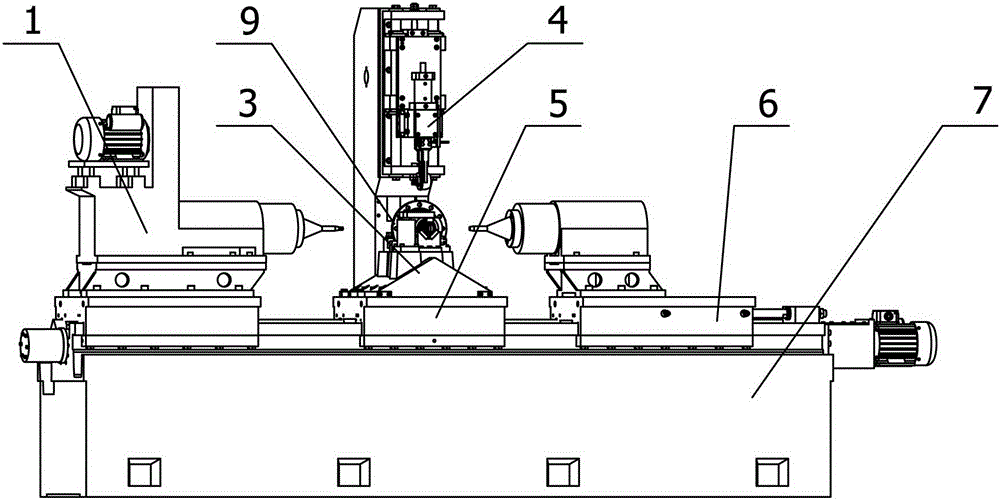
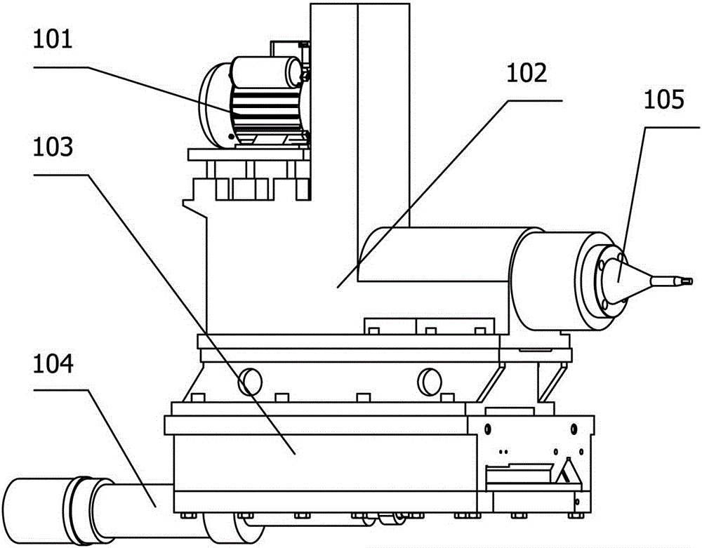
[0022] Depend on Figure 1 to Figure 5 Given, the present invention comprises lathe 7, and lathe 7 is provided with the left sliding table mechanism 1 that places on lathe 7 slide rails, middle sliding table mechanism 5, right sliding table mechanism 6, places the middle sliding table mechanism 5 rear parts The manipulator mechanism 4, the middle slide mechanism 5 is provided with a differential case clamp 3, the left slide mechanism 1 includes a left slide body 103 that can slide left and right and is fixed on the slide rail, the left slide body The right part of 103 is rotated and fixed with a left connecting rod 105, and the left connecting rod 105 is connected to the motor 101 placed on the left sliding table body 103 through the transmission box 102, and the first hydraulic oil cylinder is connected between the left...


PUM


Abstract

The invention relates to a machine tool for coarse and fine reaming of the inner spherical surface, the outer spherical surface and the end face of a differential shell. The machine tool solves the problem that an existing machine tool for manufacturing differential shells is low in machining efficiency, poor in universality, and not suitable for machining of differential shells of different types in a small-scaled mode. The machine tool comprises a machine tool body. A left sliding table mechanism, a middle sliding table mechanism, a right sliding table mechanism and a mechanical arm mechanism are arranged on the machine tool body. The left sliding table mechanism, the middle sliding table mechanism and the right sliding table mechanism are arranged on a slide rail of the machine tool. The mechanical arm mechanism is arranged on the rear portion of the middle sliding table mechanism. A differential shell clamp is arranged on the middle sliding table mechanism. The left sliding table mechanism comprises a left sliding table which slides leftwards and rightwards on the slide rail and is fixed to the slide rail. A left connection rod is rotatably fixed to the right portion of the left sliding table and connected with a motor located on the left sliding table through a transmission case. A first hydraulic cylinder is connected between the left side of the left sliding table and the machine tool body. The machine tool is suitable for small-scale production after being regulated in a one-off mode, is high in automatic production degree, low in cost, environmentally friendly, low in labor intensity, high in efficiency and suitable for small-scale production, and saves energy.

Description

technical field [0001] The invention relates to the field of differential case processing, in particular to a machine tool for rough and fine spot-sinking of the inner and outer spherical surfaces and end faces of the differential case. Background technique [0002] With the development of social economy, people's living standards are getting higher and higher. Cars have entered most families. Now there are many kinds of cars in society, and the production quantity is also increasing year by year. However, the differential case is a must for cars. One of the indispensable parts, so the demand for differential housings has also increased sharply. At present, the differential housings are developing in the direction of small batches and multiple varieties, but at present, the processing of differentials in my country is generally used. The lathe is manually processed by clamping the workpiece with a triangular chuck. This processing method has low efficiency and poor versatility...

Claims


Application Information

Patent Timeline
Patent Type & Authority Patents(China)
IPC IPC(8): B23Q5/26B23Q5/40B23Q3/08B23Q3/157
CPCB23Q3/082B23Q3/157B23Q5/26B23Q5/402
Inventor 何强李向东张宝利王敏李占君李丽丽
Owner ANYANG INST OF TECH
Why Eureka
Try Eureka