
Machining method of supercharger impeller blade based on on-machine measurement

An impeller blade and processing method technology, applied in metal processing equipment, measuring/indicating equipment, metal processing mechanical parts and other directions, can solve the problems of difficult to accurately locate the processing benchmark, unable to process deformation repair and reprocessing, etc., to improve the pass rate and Processing efficiency, meeting blade surface profile tolerance requirements, and saving production costs

Active Publication Date: 2018-02-09
中国船舶集团有限公司第七一一研究所
View PDF6 Cites 0 Cited by
  • Summary
  • Abstract
  • Description
  • Claims
  • Application Information

AI Technical Summary

Problems solved by technology

If this off-line measurement method needs to compensate and control the measured machining deformation, the impeller needs to be returned to the machine tool for repair and reprocessing, but at this time the machining reference will be difficult to locate accurately, so that the machining deformation cannot be accurately repaired and reprocessed

Method used


Image

  • Machining method of supercharger impeller blade based on on-machine measurement
  • Machining method of supercharger impeller blade based on on-machine measurement
  • Machining method of supercharger impeller blade based on on-machine measurement

Examples


Embodiment Construction

[0023] The present invention will be further described below in conjunction with the accompanying drawings.

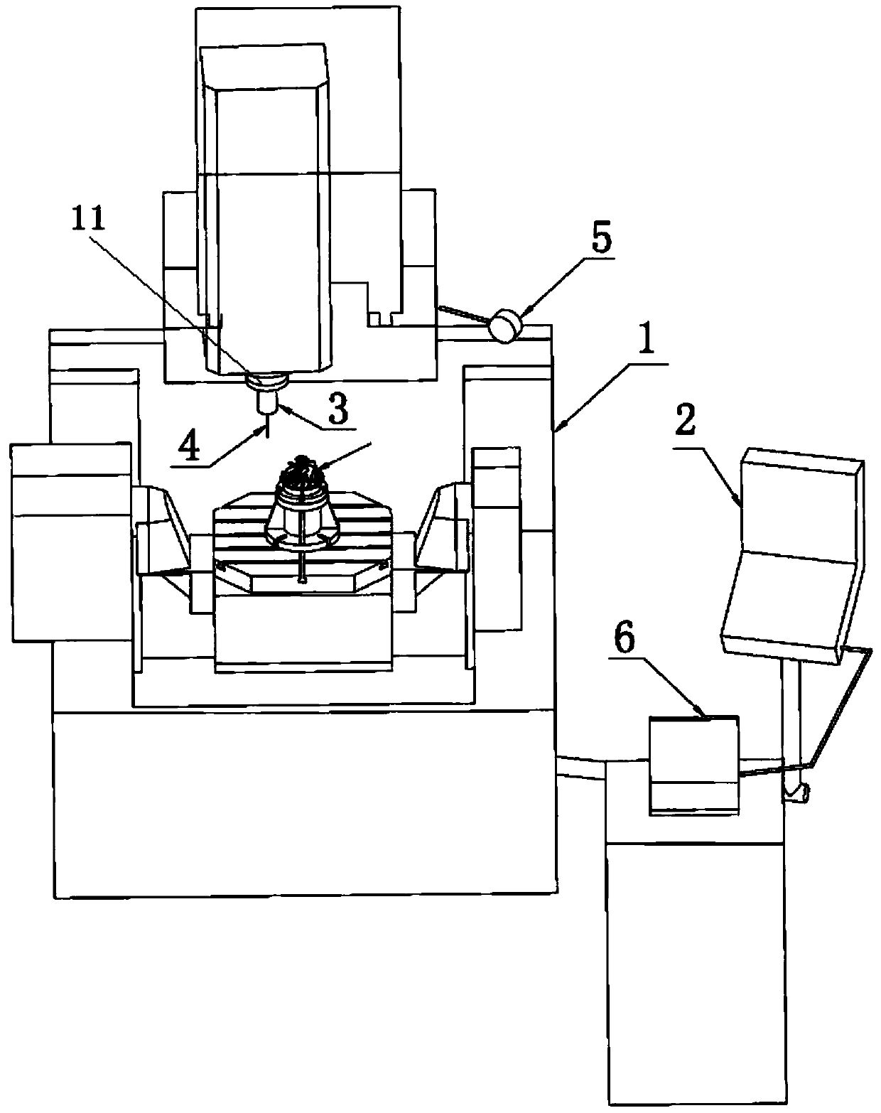
[0024] figure 1 A hardware system for implementing on-machine measurement of the present invention is shown, including a numerical control machine tool 1 , a numerical control system 2 , a touch probe and a computer 6 . The trigger probe includes a probe body 3 , a probe 4 and a receiver 5 . One end of the probe body 3 is connected with the probe 4 , and the other end is installed on the spindle 11 of the CNC machine tool. When measuring the blade of the impeller 9, the probe body contacts the measuring point on the blade through the probe 4 to obtain the coordinate value of the measuring point, and transmits the measured coordinate value of the measuring point to the receiver 5 by radio; the receiver 5 is connected with the numerical control system 2, and transmits the received measuring point coordinate value conversion to the numerical control system 2. The compu...


PUM


Abstract

The invention discloses a supercharger impeller blade machining method based on on-machine measuring. The supercharger impeller blade machining method includes: step a, calibrating a triggering-type measuring head; step b, according to a blade three-dimensional theoretic model, setting m measuring workstation coordinate systems, and planning a measuring path; step c, generating a measuring program according to the measuring path, and installing the measuring program in a numerical control system; step d, subjecting blades to rough machining, and mounting the triggering-type measuring head on a spindle of a numerical control machine tool; step e, running the measuring program, driving the triggering-type measuring head to move, and storing measuring point coordinate values; step f, transmitting the measuring point coordinate values of the blades to a computer, performing multi-workstation data aligning on the measuring point coordinate values by the computer, performing comparative calculation with the blade three-dimensional theoretic model to acquire blade machining deformation quantity and deformation rule; step g, calculating blade finish machining reverse compensation allowance, and performing blade finish machining according to the reverse compensation allowance. By the supercharger impeller blade machining method, thermal treatment process is omitted, and the problems of demounting, repairing and repositioning for off-line measuring are solved.

Description

technical field [0001] The invention relates to a method for processing impeller blades of a supercharger. Background technique [0002] The impeller is a key part of the supercharger, and its manufacturing level directly affects the performance of the supercharger. At present, the shapes of the impeller blades are mostly complex free-form surfaces, with serious distortion and thin thickness, and the thickness of some blade edges is even less than 1mm. Processing deformation occurs, so that the dimensional accuracy requirements of the blade cannot be met. [0003] Some small impellers with thinner thickness have excessive deformation after rough machining of the blades, resulting in undercutting of the blades in finishing. In this case, it is necessary to remove the impeller from the processing machine tool for quenching and tempering heat treatment after rough machining of the blades, and then return to the processing machine tool for semi-finishing and finishing of the b...

Claims


Application Information

Patent Timeline
Patent Type & Authority Patents(China)
IPC IPC(8): B23Q17/20B23Q23/00
CPCB23P15/02B23Q17/20
Inventor 张纪可宋明忠程世昌徐彦
Owner 中国船舶集团有限公司第七一一研究所
Learn More