
Workpiece deburring device

A processing equipment and deburring technology, used in metal processing equipment, grinding/polishing equipment, machine tools suitable for grinding the edge of workpieces, etc., which can solve complex curved surfaces, different processing accuracy requirements, and high costs for robots and machining centers. problem, to achieve the effect of low cost, lightweight cost, and small force on the tool

Active Publication Date: 2015-05-20
SMC (BEIJING) MFG CO LTD +1
View PDF6 Cites 3 Cited by
  • Summary
  • Abstract
  • Description
  • Claims
  • Application Information

AI Technical Summary

Problems solved by technology

The curved surface of the workpiece is complex, and the processing accuracy requirements of different positions are also different. There is no related automation equipment, and manual operation is required in most cases.
[0003] In order to meet the precision requirements, special equipment can be designed for specific castings. At present, the equipment that can meet high degree of freedom processing includes robots and machining centers. However, the cost of robots and machining centers is relatively high, which does not meet investment expectations.

Method used


Image

  • Workpiece deburring device
  • Workpiece deburring device
  • Workpiece deburring device

Examples


Embodiment Construction

[0029] The present invention will be described in detail below in conjunction with examples. Wherein the same components are denoted by the same reference numerals. It should be noted that the words "front", "rear", "left", "right", "upper" and "lower" used in the following description refer to the directions in the drawings, and the words "inner" and "outer ” refer to directions towards or away from the geometric center of a particular part, respectively.

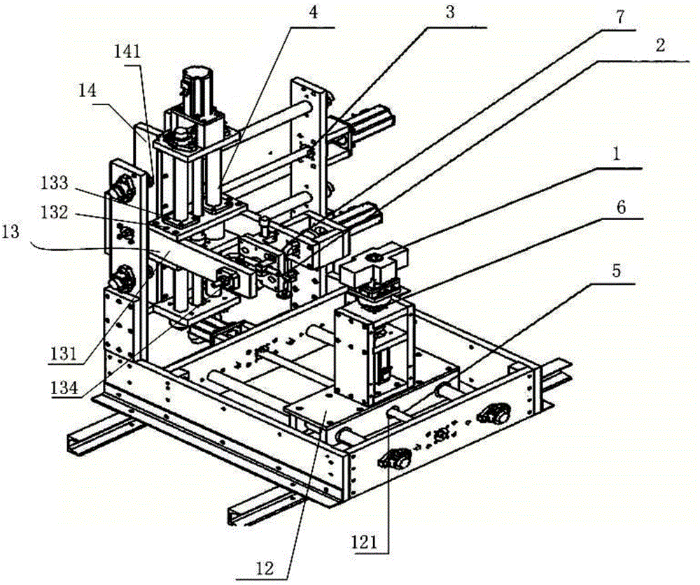
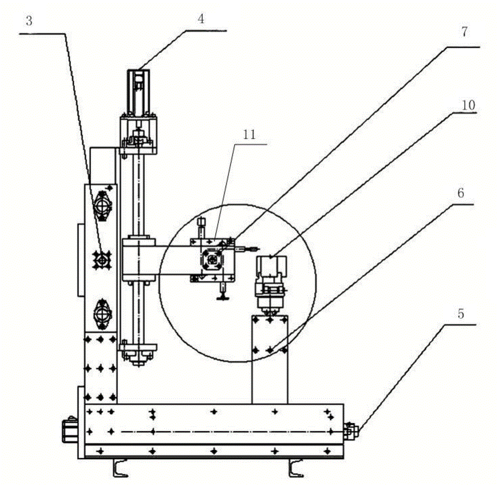
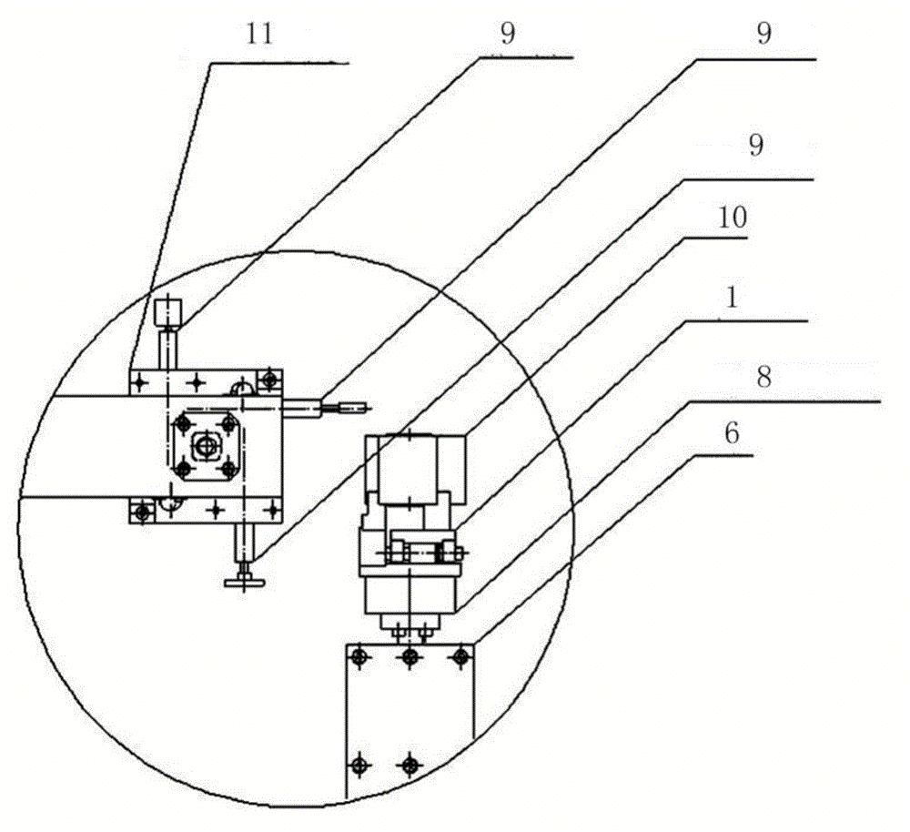
[0030] figure 1 A three-dimensional view of the structure of the workpiece deburring processing equipment provided by the embodiment of the present invention, figure 2 The front view of the workpiece deburring processing equipment provided by the embodiment of the present invention, image 3 for figure 2 A partial enlargement of the Figure 4 It is a top view of the workpiece deburring processing equipment provided by the embodiment of the present invention.

[0031] The embodiment of the present invention provides...


PUM


Abstract

The invention discloses a workpiece deburring device which comprises a workpiece frame and a tool frame. The workpiece deburring device further comprises a first horizontal shaft, a first vertical shaft, a second horizontal shaft, a second vertical shaft and a third horizontal shaft. The first horizontal shaft and the third horizontal shaft are parallel to each other. The second horizontal shaft is perpendicular to the first horizontal shaft and the third horizontal shaft. The workpiece frame is installed on the second vertical shaft which is installed on the second horizontal shaft through a first connecting box body. The tool frame is installed on the third horizontal shaft and rotates around the third horizontal shaft. The third horizontal shaft is installed on the first vertical shaft through a second connecting box body. The first vertical shaft is installed on the first horizontal shaft through a third connecting box body. According to the workpiece deburring device, on the basis of low cost, the multi-freedom-degree flexible machining requirements are met, different grinding tools can be switched for a single workpiece, different workpieces can be switched as well, multiple purposes can be achieved through one device, and the investment efficiency is maximized.

Description

technical field [0001] The invention relates to mechanical processing technology, in particular to a workpiece deburring processing equipment. Background technique [0002] Many workpieces require deburring after preliminary machining, such as metal castings and plastic parts. The curved surface of the workpiece is complex, and the machining accuracy requirements of different positions are also different. There is no related automation equipment, and manual operation is required in most cases. [0003] In order to meet the precision requirements, special equipment can be designed for specific castings. At present, the equipment that can meet the high degree of freedom processing includes robots and machining centers. However, the cost of robots and machining centers is relatively high, which does not meet investment expectations. Contents of the invention [0004] The invention provides a workpiece deburring processing equipment to meet the requirements of flexible proces...

Claims


Application Information

Patent Timeline
IPC IPC(8): B24B9/04B24B9/20
CPCB24B9/04B24B9/20
Inventor 赵彤李东亮
Owner SMC (BEIJING) MFG CO LTD
Learn More