Assembly of a plant for gas separation

A gas separation and assembly method technology, which is applied in cold treatment separation, lighting and heating equipment, industrial buildings, etc., can solve the problems of large separation column size and transportation trouble, and achieve the effect of saving material cost and minimizing consumption.

Inactive Publication Date: 2009-05-13
LINDE AG
View PDF2 Cites 0 Cited by
  • Summary
  • Abstract
  • Description
  • Claims
  • Application Information

AI Technical Summary

Problems solved by technology

In the first case, due to the large size of the separation column of this equipment, it is usually difficult to transport
The second option requires a lot of ass

Method used


Image

  • Assembly of a plant for gas separation

Examples


Embodiment Construction

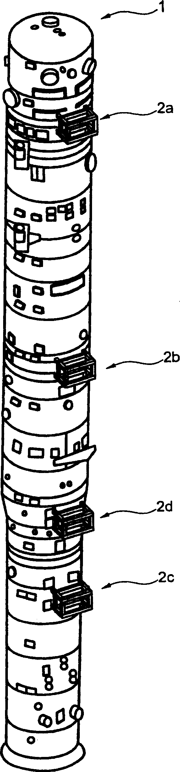
[0029] figure 1A separation column 1 with tube bridge modules 2a-2d is shown, which is installed in a gas separation device according to the assembly method of the present invention. The separation column 1 is prefabricated in a workshop and equipped with pipe bridge modules 2a-2d. On the construction site, the separation column 1 is supported horizontally, so that the pipe bridge modules 2a-2d are located on the upper half of the jacket along an axis parallel to the preferred axis of the separation column 1. Here, the installation of these tube bridge modules 2a-2d can be carried out completely or partially in the workshop or on the construction site. The assembly of the accessories is at least partially carried out on the tube bridge modules 2a-2d with the separation column 1 being horizontally supported. By assembling the accessories in a horizontal orientation, only a small scaffold at the height of the diameter of the separation column 1 is required. Almost all work is carri...


PUM


Abstract

The invention relates to an assembly method of a gas separation device comprising at least a separating column (1) and a casing device for bounding the separation column (1). The separation column (1) is manufactured in advance in a manufacturing factory and is equipped with a pipe bridge module. The column (1) is horizontally supported on a construction site so that the pipe bridge module (2a-2d) is mounted on an upper part of an outer casing along a parallel axis to a preferable axis of the separation column (1). Thus the pipe bridge module (2a-2d) can be fully or partially mounted on the peripheral surface of the separation column and accessory portions are mounted in the manufacturing factory or on the construction site. Accessories are at least partially assembled on the pipe bridge module (2a-2d) when the separation column (1) is horizontally supported. Only a small scaffold in the separation column (1) diameter height is needed by assembling the accessories in the horizontal orientation. Almost all the work is done in a plain place. In parallel with the horizontal assembly of the accessories on the separation column (1), the casing device is processed to half of the height in vertical direction, wherein the upper part is kept open. After the separation column (1) is pricked as a vertical orientation and is guided in the casting device from above, the assembly is finished and the casing device is closed.

Description

Technical field [0001] The present invention relates to a method for assembling a gas separation device. The gas separation device includes at least one separation column and a sheathing device surrounding the separation column, wherein the separation column has a preferred axis and different accessories fixed on it, For example, pipes, supply and discharge devices, valves and / or instruments. Background technique [0002] In the construction of gas separation equipment, such as cryogenic air separation equipment, there is basically the option of prefabricating the equipment in the factory floor or assembling the equipment components on the construction site as much as possible. In the first case, due to the large size of the separation column of this equipment, it is usually very troublesome to transport. The second solution requires a lot of assembly work to be performed in an unsuitable environment. An important part of this assembly is the placement of a separation column in a...

Claims


Application Information

Patent Timeline
IPC IPC(8): F25J3/04
CPCE04H5/10F25J2290/42F25J2290/44F25J3/04945F25J3/0489
Inventor R·尚达
Owner LINDE AG
Why Eureka
Try Eureka