

Suction cup
A suction cup and body technology, applied in the suction cup field, can solve the problems of instability and weakened suction, and achieve the effect of good friction effect
- Summary
- Abstract
- Description
- Claims
- Application Information
AI Technical Summary
Problems solved by technology
Method used
Image

Examples
Embodiment Construction
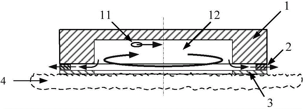
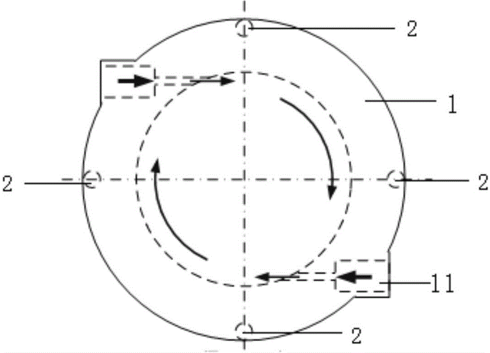
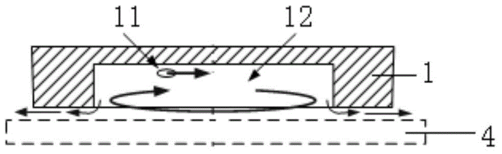
[0030] refer to Figure 1a and 1b , the suction cup includes a suction cup body 1, the suction cup body 1 has a cavity 12 with a circular cross section, the cavity 12 has a closed end face and an open end face, and the open end face forms an end face for absorbing objects, so The wall surface of the cavity 12 is provided with a tangential nozzle 11, and also includes an annular partition 3 and a spacer 2, and the spacer 2 is arranged on the bottom surface of the suction cup body 1 at intervals, and the annular partition The upper surface of 3 is fixedly connected to the outer edge of the bottom surface of the suction cup body 1 through the pad 2; the pad 2 covers part of the area of the annular partition 3, and the distance between the pad and the pad forms the suction cup body 1 A fixed flow channel between the outer edge of the bottom surface and the annular partition 3, the fixed flow channel communicates with the inner cavity 12 and the peripheral environment.
[0031]...
PUM
 Abstract
Description
Claims
Application Information