Cam-driven-type dual-station stamping device

A punching device and driving technology, applied in the field of punching device and cam-driven punching device, can solve the problems of high manufacturing precision requirements of hydraulic components, high operation and maintenance costs, complex hydraulic system design, etc. The effect of low cost and high degree of automation

Inactive Publication Date: 2015-05-20
XIAN ZHIYUE ELECTROMECHANICAL TECH
View PDF0 Cites 10 Cited by
  • Summary
  • Abstract
  • Description
  • Claims
  • Application Information

AI Technical Summary

Problems solved by technology

The stamping device generally uses a hydraulic cylinder to directly drive the stamping head to stamp the workpiece. This method is not labor-saving. In addition, hydraulically driven stamping devices generally have problems such as complex hydraulic system design, high manufacturing precision requirements for hydraulic components, and high operating and maintenance costs.

Method used


Image

  • Cam-driven-type dual-station stamping device

Examples


Embodiment Construction

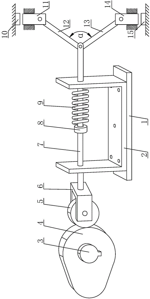
[0021] Such as figure 1 A cam-driven double-station stamping device shown includes a U-shaped bracket 2 for supporting the push rod 7, a base 1 for supporting the U-shaped bracket 2, and a base 1 for driving the push rod 7 forward The sliding disc cam 4 also includes a back-moving spring 9 for driving the reset of the push rod 7, a stamping head one 11 for stamping the workpiece one 10 and a stamping head two 14 for stamping the workpiece two 15; The rod 7 is slidably installed on the U-shaped bracket 2, the middle part of the push rod 7 is fixedly provided with a spring stop 8, and the return spring 9 is arranged between the spring stop 8 and the U-shaped bracket 2, One end of the push rod 7 is rotated with a roller 5 through the roller frame 6, and the disc cam 4 is installed on the end of the power shaft 3, and the other end of the push rod 7 is respectively connected to an end of the transmission rod 12 and the end of the drive rod 12. One end of the transmission rod two ...


PUM


Abstract

The invention discloses a cam-driven-type dual-station stamping device which comprises a U-shaped support for supporting a pushing rod. The pushing rod is installed on the U-shaped support in a sliding mode. An elastic stop block is fixedly arranged in the middle of the pushing rod. A reset spring is arranged between the elastic stop block and the U-shaped support. A roller is installed at one end of the pushing rod in a rotating mode through a roller carrier. A disc cam is installed at the end of a power shaft. The other end of the pushing rod is hinged to one end of a first transmission rod and one end of a second transmission rod. The other end of the first transmission rod is hinged to a first stamping head. The other end of the second transmission rod is hinged to a second stamping head. The cam-driven-type dual-station stamping device has the advantages of being reasonable in design, convenient to operate, high in automation degree, high in production efficiency, long in service life, wide in application range, low in production cost and convenient to use and popularize and saving time and labor.

Description

technical field [0001] The invention belongs to the technical field of mechanical processing, and relates to a stamping device, in particular to a cam-driven stamping device with double stations. Background technique [0002] Stamping refers to the use of molds to make metal sheets into various sheet-shaped parts, shells, and container workpieces on a punching machine, or to make pipe fittings into various tubular workpieces. In national production, compared with traditional mechanical processing, the stamping process has the advantages of saving materials and energy, high efficiency, low technical requirements for operators, and the ability to produce products that cannot be achieved by mechanical processing through various mold applications. Therefore, Its use is more and more extensive. The stamping device generally uses a hydraulic cylinder to directly drive the stamping head to stamp the workpiece. This method is not labor-saving. In addition, hydraulically driven stam...

Claims


Application Information

Patent Timeline
Patent Type & Authority Applications(China)
IPC IPC(8): B30B1/14
CPCB30B1/14
Inventor 秦玉春
Owner XIAN ZHIYUE ELECTROMECHANICAL TECH
Why Eureka
Try Eureka