Multifunctional flying saucer

A multi-functional, flying saucer technology, applied in the field of aircraft, can solve the problems of delayed rescue opportunity, high difficulty, and use of aircraft, and achieve the effect of easy promotion, wide application and strong stability

Active Publication Date: 2015-05-20
丁乃祥
View PDF7 Cites 10 Cited by
  • Summary
  • Abstract
  • Description
  • Claims
  • Application Information

AI Technical Summary

Problems solved by technology

Now amphibious vehicles etc. have also been vigorously developed, but they cannot be used as aircraft, and the running speed on water is slow, such as carrying out rescue work such as search and rescue, which will delay the rescue opportunity; Gliding on water to achieve

Method used


Image

  • Multifunctional flying saucer
  • Multifunctional flying saucer
  • Multifunctional flying saucer

Examples


Embodiment 1

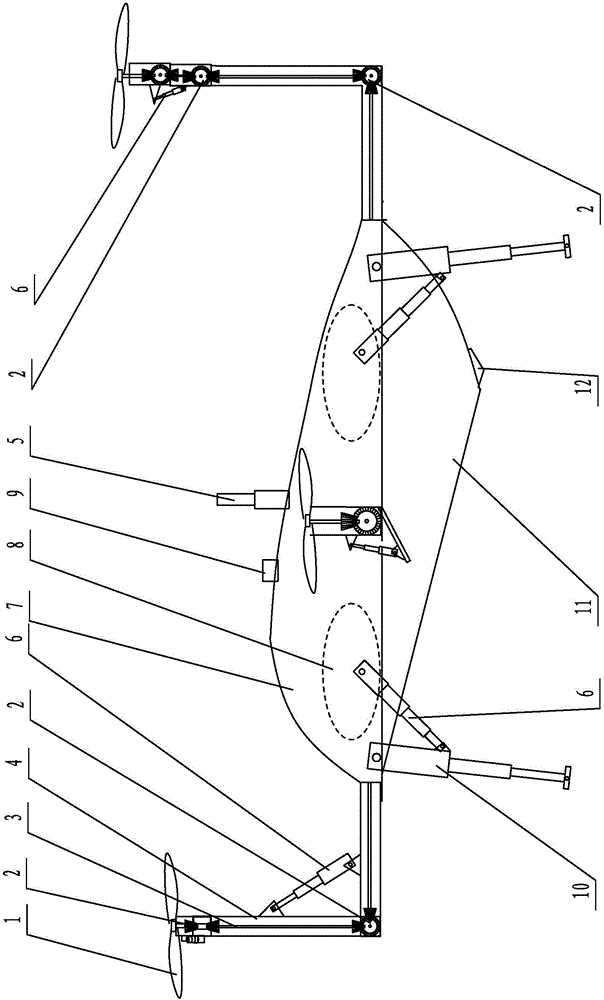
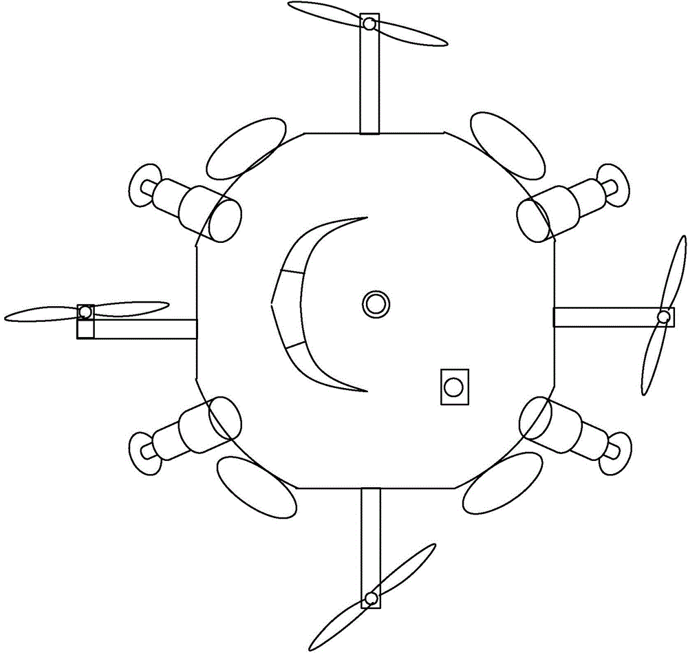
[0026] Such as figure 1 and image 3 As shown, the multifunctional flying saucer of the present invention comprises a circular fuselage 7, the bottom of the fuselage 7 is flat and the upper part protrudes in the shape of a wing, and four mounting rods 4 are evenly distributed on the edge of the fuselage 7, and a transmission rod 3 is arranged in the mounting rod 4. , the transmission rod 3 is connected to the engine inside the fuselage 7 through the clutch;

[0027] Two sections of installation rods 4 are continuously hinged on the front installation rod 4, and transmission rods 3 are arranged inside the installation rods 4, and the ends of the installation rods 4 are hinged together. Driven by the oil cylinder 6, the base of the oil cylinder 6 and the piston rod are respectively hinged on the adjacent installation rod 4, the last installation rod 4 is provided with a propeller 1, and the propeller 1 is fixedly connected with the transmission rod 3, and the expansion and cont...

Embodiment 2

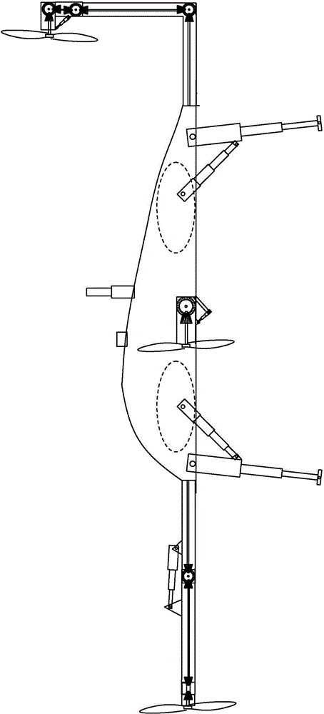
[0039] Such as figure 2 and image 3 Shown, the fuselage is that the bottom surface is a plane, and the fuselage is wing-shaped, and other structures are the same as in embodiment 1, so that when flying at high speed in the air, the air pressure difference between the upper and lower sides of the fuselage gives the fuselage a certain lift, which is beneficial to flight.

Embodiment 3

[0041] The fuselage is elliptical, which is good for driving in water.


PUM


Abstract

The invention relates to a multifunctional flying saucer, and belongs to the field of aircrafts. The multifunctional flying saucer comprises a circular body, wherein the lower portion of the body is flat while the upper portion of the body is protruded and is in the shape of an aerofoil; four mounting rods are uniformly distributed at the edge of the body; a transmission rod is arranged in each mounting rod; and each transmission rod is connected with an engine in the body through a corresponding clutch. The multifunctional flying saucer can run on water, on land and in air, is economical and practical, is convenient to popularize and use and can be used for rescue operation.

Description

technical field [0001] The invention relates to a multifunctional flying saucer, which belongs to the field of aircraft. Background technique [0002] In the field of transportation, it is divided into three types of transportation, water, land and air. Common water, land and air transportation can only be operated in their corresponding fields. Now amphibious vehicles etc. have also been vigorously developed, but they cannot be used as aircraft, and the running speed on water is slow, such as carrying out rescue work such as search and rescue, which will delay the rescue opportunity; Gliding on water to achieve take-off and landing requires a long journey, and cannot achieve vertical lift, making fixed-point landing difficult; the aircraft under development that can travel on land is similar to a glider, with wings with a large wingspan, and it is extremely difficult to promote . Contents of the invention [0003] According to the deficiencies in the above prior art, th...

Claims


Application Information

Patent Timeline
IPC IPC(8): B60F5/02B64C27/28
Inventor 丁乃祥
Owner 丁乃祥
Why Eureka
Try Eureka