
A pure electric passenger car air conditioning system and its application method

An air-conditioning system and passenger car technology, applied to vehicle components, air handling equipment, irreversible cycle compressors, etc., can solve problems that affect the performance of passenger car air-conditioning, easy to accumulate dust, reduce stability and reliability, etc.

Active Publication Date: 2016-03-23
杭州祥河实业有限公司
View PDF4 Cites 0 Cited by
  • Summary
  • Abstract
  • Description
  • Claims
  • Application Information

AI Technical Summary

Problems solved by technology

The existing passenger car air conditioner comprises a compressor, a condenser, a liquid storage drier, an expansion valve, a top cover, an evaporator and a blower, and the compressor, condenser, liquid storage drier, expansion valve, and evaporator are arranged between The pipes are connected into a closed system. The condenser and evaporator are all made of copper tubes and aluminum sheets with outdated technology. They are randomly arranged, and the heat dissipation effect is not good. The low efficiency affects the performance of the passenger car air conditioner, especially the high energy consumption.
[0003] Since the condenser fan is often set to face the outside of the vehicle body, a large amount of dust tends to accumulate when the air conditioner is not in use
This affects the operating performance of the equipment, and will shorten the service life of the equipment, reduce the stability and reliability of its operation

Method used


Image

  • A pure electric passenger car air conditioning system and its application method
  • A pure electric passenger car air conditioning system and its application method
  • A pure electric passenger car air conditioning system and its application method

Examples


Embodiment Construction

[0018] Refer below Figure 1-5 The present invention will be described.

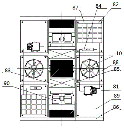
[0019] refer to figure 1 A pure electric passenger car air-conditioning system shown includes two independently controlled refrigeration units, and the refrigeration unit includes a compressor 81, a parallel flow condenser 82, a parallel flow evaporator 83, a liquid receiver dryer 84, and an H-type expansion Valve 85, housing base 86, condenser chamber cover 87, condensing fan cover 88, compressor chamber cover 89, evaporating fan 90 and condensing fan 10; the compressor 81, parallel flow condenser 82, parallel flow The evaporator 83, liquid storage drier 84, H-type expansion valve 85, evaporation fan 90 and condensation fan 10 are all arranged on the housing base 86, and the H-type expansion valve 85 is fixed on the parallel flow evaporator 83 Above, the receiver drier 84 and the compressor 81 are connected in parallel between the parallel flow condenser 82 and the H-type expansion valve 85, and the c...


PUM


Abstract

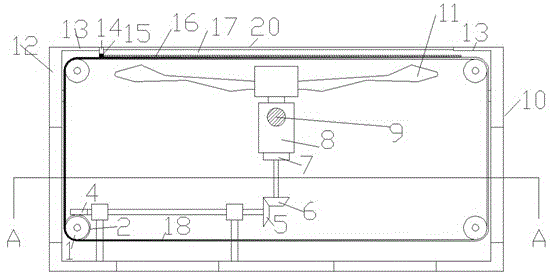
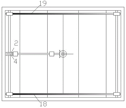
The invention discloses an air-conditioning system of a pure electric passenger car. The air-conditioning system comprises two individual refrigerating units which are in 180-degree distribution and are both 'L'-shaped; each refrigerating unit comprises a compressor device (81), a parallel flow condenser device (82), a parallel flow evaporator device (83), an evaporation fan device (90) and a condensing fan device (10), wherein the condensing fan device (10) comprises a box body outer shell (12); the upper side surface of the box body outer shell (12) is provided with an empty window area (17); a fan (11) is arranged close to the empty window area (17) and is arranged in an empty cavity of the box body outer shell (12); a rotation shaft of the fan (11) is vertical, and the lower end of the rotation shaft and the upper end of a driving device (8) are connected in a power mode; the side part of the driving motor (8) is fixedly connected with the inner wall of the box body outer shell (12) by a fixed beam (9).

Description

technical field [0001] The invention relates to an air conditioning system, in particular to a pure electric passenger car air conditioning system. Background technique [0002] The passenger car air conditioning system is a device that realizes cooling, heating, ventilation and air purification of the air in the passenger car. It can provide a comfortable riding environment for the passengers, reduce the driver's fatigue intensity and improve driving safety. The air conditioning unit has become one of the symbols to measure whether the car is fully functional. With the development of my country's urban public transport and tourism, a large number of air-conditioned buses are on the market, and there is an increasing demand for passenger car air-conditioning maintenance personnel. The existing passenger car air conditioner comprises a compressor, a condenser, a liquid storage drier, an expansion valve, a top cover, an evaporator and a blower, and the compressor, condenser,...

Claims


Application Information

Patent Timeline
Patent Type & Authority Patents(China)
IPC IPC(8): B60H1/00B60H1/32F25B1/10F25B49/02
CPCB60H1/00021B60H2001/00078B60H2001/00114
Inventor 夏国明冯罗平张迪群
Owner 杭州祥河实业有限公司
Learn More