Steel wire rope yaw winding mechanism

A technology of winding mechanism and steel wire rope, which is applied in the direction of clockwork mechanism and hoisting device, can solve the problems of increasing the cost of the whole machine, increasing maintenance cost, accelerating the wear of wire rope and drum pulley, etc., and achieves convenient use and maintenance. Simple and reliable, easy maintenance cost effect

Active Publication Date: 2017-01-25
WUXI HUADONG HEAVY MACHINERY
View PDF9 Cites 0 Cited by
  • Summary
  • Abstract
  • Description
  • Claims
  • Application Information

AI Technical Summary

Problems solved by technology

Increasing the diameter of the reel will inevitably require the wheelbase of the reducer to increase, that is, the selection of the reducer will increase, which greatly increases the cost of the whole machine.
The general practice in the current technology is to increase the length of the drum and increase the stroke of the steel wire rope on the drum, while the guide pulley of the existing wire rope is a fixed installation method, that is, the increase of the stroke of the steel wire rope on the drum will increase accordingly. The rope outlet angle of the wire rope on the drum is reduced. If the rope outlet angle is too large, it will cause the wire rope to jump, which will speed up the wear of the wire rope, drum, and pulley, and increase the maintenance cost for future use.

Method used


Image

  • Steel wire rope yaw winding mechanism
  • Steel wire rope yaw winding mechanism

Examples


Embodiment Construction

[0010] The present invention will be further described below in conjunction with specific drawings.

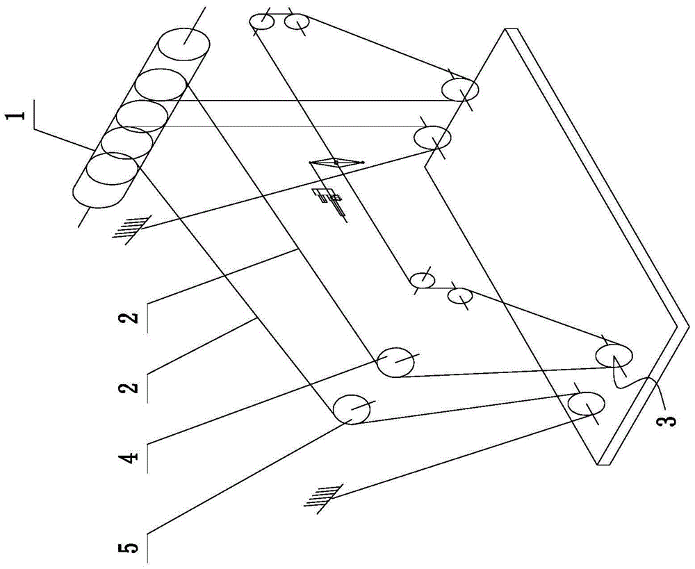
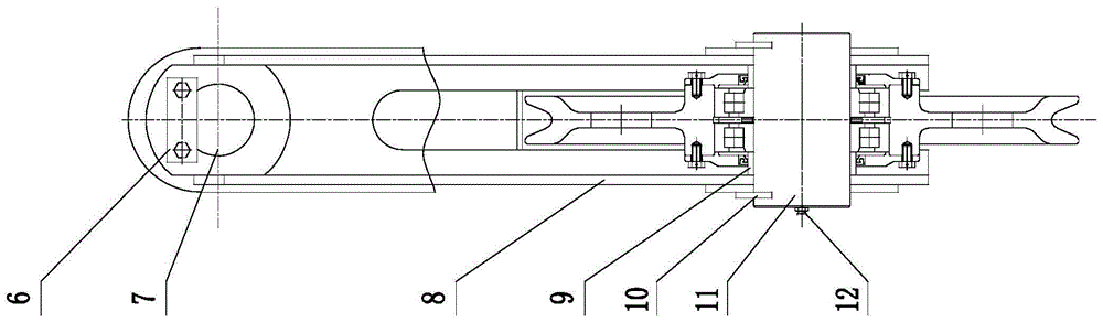
[0011] Such as Figure 1 ~ Figure 2 As shown: the wire rope yaw winding mechanism includes a drum 1, a wire rope 2, a pulley block 3, a first yaw pulley 4, a second yaw pulley 5, a first stop plate 6, a first hinge shaft 7, and a yaw Pulley bracket 8, spacer collar 9, second stop plate 10, second hinge shaft 11, oil cup 12, etc.

[0012] Such as figure 1 As shown, the present invention includes a drum 1 and a pulley block 3. The pulley block 3 is composed of a plurality of pulleys. A wire rope 2 is wound on the drum 1, and the wire rope 2 passes through each pulley of the pulley block 3 in turn; the first in the pulley block 3 The yaw pulley 4 and the second yaw pulley 5 are located on one side of the drum 1, and the first yaw pulley 4 and the second yaw pulley 5 are respectively mounted on the yaw pulley bracket 8;

[0013] Such as figure 2 As shown, a first hinge shaft 7 is prov...


PUM


Abstract

The invention relates to a steel wire rope deflection winding mechanism. The mechanism comprises a coiling block and a pulley block, wherein the pulley block is composed of multiple pulleys, and a steel wire rope is wound around the coiling block and passes through each pulley of the pulley block. The mechanism is characterized in that the first deflection pulley and the second deflection pulley in the pulley block are located on one side of the coiling block and arranged on a deflection pulley support, a first hinge shaft is arranged on the upper portion of the deflection pulley support, a second hinge shaft is arranged on the lower portion of the deflection pulley support, the first hinge shaft is perpendicular to the second hinge shaft, the first deflection pulley and the second deflection pulley are installed on the second hinge shaft, spacing collars are arranged on the two sides of the first deflection pulley respectively, and spacing collars are arranged on the two sides of the second deflection pulley respectively. By the adoption of the mechanism, jumping of the hoisting steel wire rope can be prevented, abrasion of the steel wire rope, the coiling block and the pulleys is reduced, and usage and maintenance in the later stage are facilitated, and maintenance cost is reduced.

Description

Technical field [0001] The invention relates to a wire rope yaw winding mechanism, in particular to a lifting wire rope winding mechanism of a container gantry crane. Background technique [0002] With the development of modern logistics industry, more and more container gantry cranes are used by various port terminals. In order to improve the utilization rate of the yard, the number of layers of containers stacked in the terminal yard is increasing, which requires the lifting of the crane. The higher the height, the higher the lifting height, the larger the rope capacity of the lifting drum is required. There are generally two ways to increase the rope capacity of the lifting drum, one is to increase the diameter of the drum, and the other is to increase the length of the drum. Increasing the diameter of the reel will inevitably require the wheelbase of the reducer to increase, that is, the selection of the reducer will increase, which greatly increases the cost of the whole ma...

Claims


Application Information

Patent Timeline
Patent Type & Authority Patents(China)
IPC IPC(8): B66D1/28
CPCB66D1/28
Inventor 翁杰方厚如
Owner WUXI HUADONG HEAVY MACHINERY
Why Eureka
Try Eureka