Blowing and sucking device and method for using same

A technology of a blowing and suction device and a blowing pipe, which is applied to cleaning methods, road cleaning, construction, etc., can solve the problems of low efficiency, time-consuming and labor-intensive, and the blowing direction cannot be adjusted relative to the main body shell, etc. Increased flexibility and improved purge efficiency

A technology of a blowing and suction device and a blowing pipe, which is applied to cleaning methods, road cleaning, construction, etc., can solve the problems of low efficiency, time-consuming and labor-intensive, and the blowing direction cannot be adjusted relative to the main body shell, etc. Increased flexibility and improved purge efficiency

CN104631370AActive Publication Date: 2015-05-20POSITEC POWER TOOLS (SUZHOU) CO LTD

Image

  • Blowing and sucking device and method for using same
  • Blowing and sucking device and method for using same
  • Blowing and sucking device and method for using same

Examples


Embodiment Construction

[0030] Further details will be given below in conjunction with the accompanying drawings and preferred embodiments of the present invention.

[0031] Embodiment The preferred blowing and suction device belongs to garden electric tools, and is often used to blow off fallen leaves.

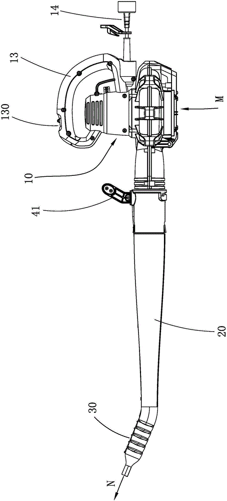
[0032] Please refer to figure 1 , figure 1 It is a schematic diagram of the blowing device 1, and the blowing device 1 uses the structure shown in the figure to realize the function of blowing, and can be used to blow off fallen leaves and collect fallen leaves into piles. The blowing device 1 includes a main body casing 10, a main handle 13 arranged on the main body casing 10, a motor and a fan (not shown in the figure) arranged in the main body casing 10, a direction adjustment mechanism and the main body casing 10. Connected blower assembly. The blowing assembly includes a blowing pipe 20 and a blowing accessory 30 connected with the blowing pipe 20 .

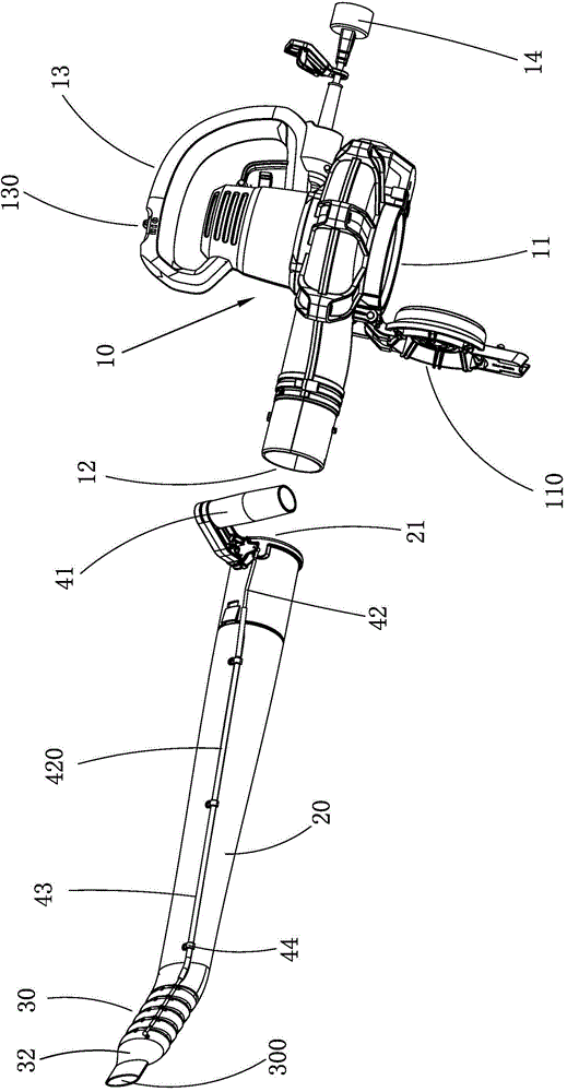
[0033] Please also refer to figure 2 ...


PUM


Abstract

The invention relates to a blowing and sucking device. The blowing and sucking device comprises a main housing, a main handle, a motor and a fan, wherein the main housing is provided with an air inlet and an air outlet; the main handle is arranged on the main housing; the motor and the fan are arranged in the main housing, and the motor drives the fan to rotate to form airflow coming in from the air inlet and going out from the air outlet. The blowing and sucking device further comprises a direction adjusting mechanism and a blowing assembly. The blowing assembly comprises an air inlet end and a blowing part, wherein the air inlet end is connected with the air outlet of the main housing, airflow is blown out from the blowing part and forms the blowing direction of the blowing and sucking device, and the direction adjustment mechanism adjusts the blowing assembly so that the blowing direction can keep in the predetermined direction. In this way, the flexibility of an air blower during use is enhanced, and blowing efficiency is improved.

Description

technical field [0001] The invention relates to a blowing and sucking device and a method for using the blowing and sucking device, in particular to a blowing and sucking device with adjustable blowing direction and a method for using the blowing and sucking device with adjustable blowing direction. Background technique [0002] The blowing device (or blower) generally includes a main body casing, a motor arranged in the main body casing and a fan driven by the motor. The main body casing is provided with an air inlet and an air outlet, and the blowing device (or blower) utilizes a rotating fan Form a directional airflow that always enters from the air inlet and blows out from the air outlet. When using the blowing function of the blower and suction device, connect the blower pipe to the air outlet of the main body shell, and the directional airflow flows through the pipe of the blower pipe to the outlet end of the blower pipe. The blowing and suction device has played a sig...

Claims


Application Information

Patent Timeline
20 May 2015
Publication
CN104631370A
IPC
E01H1/08
CPC
E01H1/0809; E01H2001/0881
Inventors
沃伦.布朗; 哈利.索默