Combined electronic lock

An electronic lock and combined technology, applied in the field of electronic locks, can solve the problems of easy opening of the cover to take out the battery, different thickness of the door panel, difficult installation, etc., and achieve the effect of simple and fast installation process, enhanced versatility and simple structure

Active Publication Date: 2015-05-20
GUANGZHOU GUUB TECH
View PDF7 Cites 1 Cited by
  • Summary
  • Abstract
  • Description
  • Claims
  • Application Information

AI Technical Summary

Problems solved by technology

[0006] The purpose of the present invention is to disclose a combined electronic lock, which solves the problem that the existing electronic lock cannot replace the lock core to cope with different installation environments, and when the thickness of the door panel is different, many accessories are required, it is difficult for users to distinguish, and it is difficult to install.
It further solves the problem that the battery cover is fastened with a buckle structure, and it is easy to open the cover to take out the battery; the battery cover is locked with screws, and the removal of the battery cover requires special tools, which is inconvenient to use
It further solves the problem of using external power supply and difficult decoding when the password is lost

Method used


Image

  • Combined electronic lock
  • Combined electronic lock
  • Combined electronic lock

Examples


Embodiment Construction

[0044] The following will clearly and completely describe the technical solutions in the embodiments of the present invention with reference to the drawings in the embodiments of the present invention. Apparently, the described embodiments are only some of the embodiments of the present invention, but not all of them.

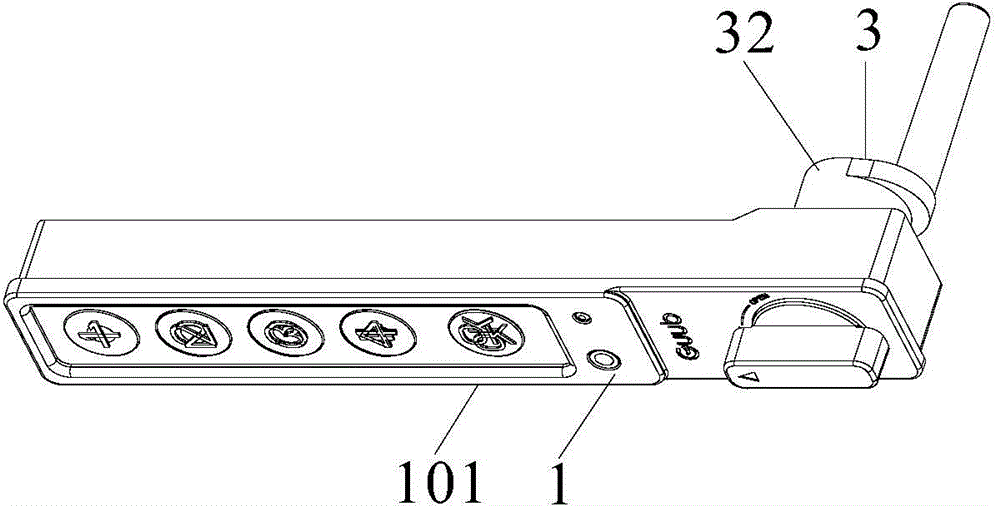
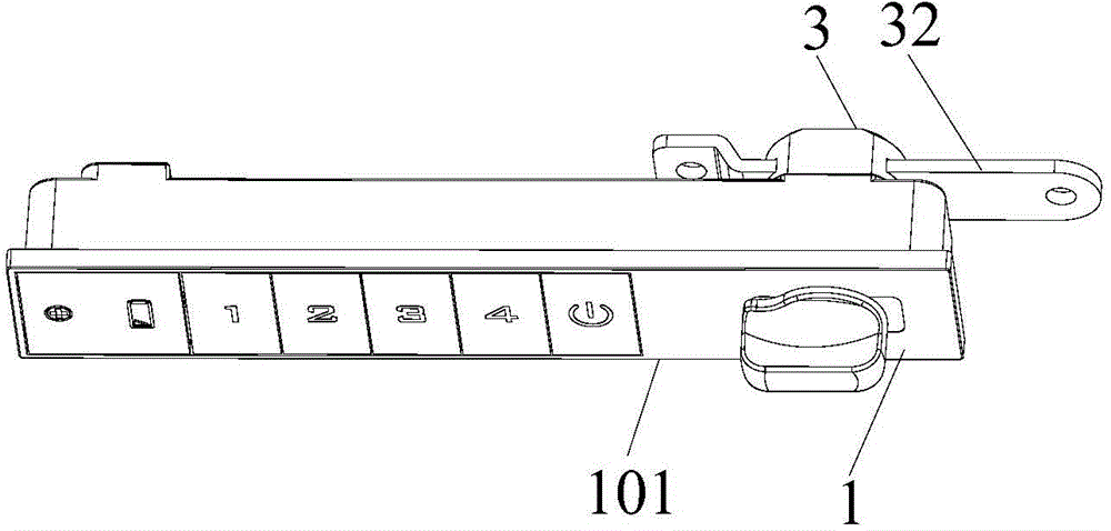
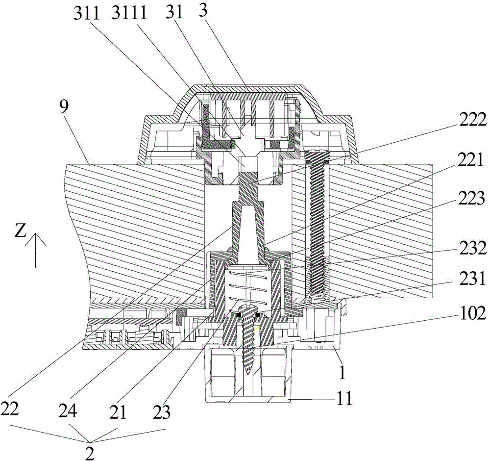
[0045] Such as Figure 3 to Figure 17 The illustrated embodiment is a combined electronic lock, comprising a lock body panel 1, a connection structure 2 connected to the lock body panel 1, and a lock cylinder 3 independent from the lock body panel 1; the lock body panel 1 includes a knob 11, and the lock cylinder 3 includes a lock cylinder rotating block 31 and a locking part 32 connected with the lock cylinder rotating block 31. The knob 11 is connected with the connection structure 2 , and the connection structure 2 is connected with the lock cylinder rotating block 31 . The knob 11 drives the lock cylinder rotating block 31 to rotate through the connecting...


PUM


Abstract

The invention discloses a combined electronic lock which comprises a lock body panel, a connecting structure and a lock cylinder. The connecting structure is connected with the lock body panel, and the lock cylinder is independent from the lock body panel. The lock body panel comprises a rotary knob. The lock cylinder comprises a lock cylinder rotating block and a locking portion connected with the lock cylinder rotating block. The connecting structure comprises a rotating cam, a connecting rod and a positioning sleeve, wherein the connecting rod is arranged inside a cavity of the rotating cam, and the rotating cam is sleeved with the positioning sleeve. The bottom of the rotating cam is connected with the rotary knob. The rotating cam is sleeved with the positioning sleeve from the top of the rotating cam. A clamping position for clamping the inner surface of the positioning sleeve is arranged at the lower portion of the connecting rod, so that the connecting rod is prevented from sliding out of the rotating cam. The upper portion of the connecting rod stretches out of the positioning sleeve to be inserted into a connecting groove in the lock cylinder rotating block, so that the connecting structure is connected with the lock cylinder rotating block. The rotary knob drives the locking cylinder rotating block through the connecting structure to rotate. By the adoption of the structure, the lock body panel and the lock cylinder are separately and independently designed, and the universality of the electronic lock is enhanced.

Description

technical field [0001] The invention relates to the technical field of electronic locks, in particular to a combined electronic lock. Background technique [0002] Common electronic lock integrated electronic lock 101 in the prior art (as figure 1 and figure 2 As shown), the lock body panel 1 and the lock cylinder 3 are integrated, and a lock body panel can only correspond to one lock cylinder, and the lock cylinder cannot be replaced according to the installation requirements, and the locking part 32 of the lock cylinder cannot be changed according to the installation environment. , resulting in a single function of the electronic lock, which cannot be used in different application environments such as cabinets and door panels. [0003] At the same time, in the prior art, when installing an ordinary electronic lock, the thickness of the door panel needs to be considered, and gaskets need to be added according to the thickness of the door panel, or connecting rods of diff...

Claims


Application Information

Patent Timeline
Patent Type & Authority Applications(China)
IPC IPC(8): E05B49/00E05B15/00H01M2/04H01M50/147
CPCY02E60/10
Inventor 李锦恭钟长林范石权
Owner GUANGZHOU GUUB TECH
Why Eureka
Try Eureka