A plunger for gas well drainage

A technology of plunger and gas well, which is applied in the field of plunger for gas well drainage, can solve the problems of high operating cost and short stable production period of gas well, and achieves the effect of increasing the time of opening well, prolonging the stable production period and avoiding frequent well shut-in.

Active Publication Date: 2017-07-07
PETROCHINA CO LTD
View PDF5 Cites 0 Cited by
  • Summary
  • Abstract
  • Description
  • Claims
  • Application Information

AI Technical Summary

Problems solved by technology

[0006] The purpose of the present invention is to solve the problems of high operating cost and short stable production period of gas wells due to frequent opening and closing of existing plungers, and provide a plunger for gas well drainage

Method used


Image

  • A plunger for gas well drainage
  • A plunger for gas well drainage
  • A plunger for gas well drainage

Examples


Embodiment 1

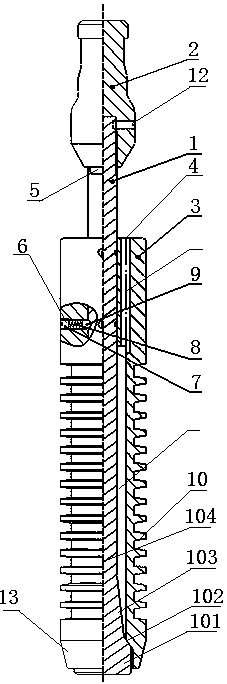
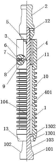
[0021] Such as figure 1 and figure 2 As shown, the present invention provides a plunger for gas well drainage, including a central rod 1, the top of the central rod 1 is fixedly connected with a fishing head 2, and the outer circumference of the central rod 1 is provided with a For the sliding outer cylinder 3, the diameter of the bottom end of the central rod 1 is greater than or equal to the inner diameter of the bottom end of the outer cylinder 3, and the bottom end of the central rod 1 is in sealing contact with the bottom end of the outer cylinder 3, and the inner surface of the outer cylinder 3 and the inner surface of the central rod 1 The outer surface forms a cavity 401 , and a plurality of through holes 4 are opened along the axial direction of the outer cylinder 3 , and the through holes 4 communicate with the cavity 401 .

[0022] Specifically, after the well is opened for production, the gas well drainage plunger is put into the tubing, and the gas well drainage...

Embodiment 2

[0026] On the basis of Embodiment 1, an annular groove 5 is provided on the outer wall of the central rod 1 along its circumference, and a circular hole 6 is provided on the wall of the outer cylinder 3 along its radial direction. A compression screw 7, a spring 8, and a lock block 9 are provided. One end of the lock block 9 is located in the annular groove 5, and the other end is located in the round hole 6. The compression screw 7 is located on the wall of the outer cylinder 3 close to the outer cylinder 3. At one end, the spring 8 is located between the locking block 9 and the compression screw 7, and the spring 8 is connected with the locking block 9 and the compression screw 7 respectively.

[0027] Specifically, one end of the central rod 1 is fixedly connected with the fishing fish head 2 with a boss, and the other end is inserted into the outer cylinder 3, and the locking block 9 and the spring 8 are sequentially loaded into the radial circular hole 6 on the upper end o...

Embodiment 3

[0031] On the basis of Embodiment 1, in order to reduce the weight of the outer cylinder 3 and reduce the gravitational force on the outer cylinder 3 sliding up and down along the central rod 1, a herringbone-shaped circular platform 10 is arranged on the wall of the outer cylinder 3 of the outer cylinder 3 ,Such as figure 1 with figure 2 As shown, the section is jagged.


PUM


Abstract

The invention provides a plunger used for gas well water drainage. The plunger used for the gas well water drainage comprises a center pole, the top end of the center pole is fixedly connected with a throwing and pulling fish head, the periphery of the center pole is sleeved with an outer cylinder capable of sliding up and down along the center pole, the diameter of the bottom end of the center pole is larger than or equal to the inner diameter of the bottom end of the outer cylinder, the bottom end of the center pole makes contact with the bottom end of the outer cylinder in a sealing mode, a cavity is formed by the inner surface of the outer cylinder and the outer surface of the center pole, a plurality of through holes are formed along the axial direction of the outer cylinder, and the through holes are communicated with the cavity. The plunder used for the gas well water drainage is applied to the plunder gas lift water drainage technology, the gas lift water drainage plunger has the functions that an gas flow channel closes in a well bottom or in the process of ascending with liquid, and the gas flow channel opens when reaches the well mouth or in the process of descending. The plunger gas lifting technology under the condition that a gas well is not closed is achieved, the well opening time of the gas well is increased, the stable production period of the gas well is prolonged, frequent well closing is avoided, and the operation cost is reduced.

Description

technical field [0001] The invention belongs to the field of oilfield drainage and gas production, and in particular relates to a plunger for gas well drainage. Background technique [0002] In the development of low-pressure gas fields and condensate gas fields, fluid accumulation in the wellbore is one of the main problems restricting the stable and high production of gas wells. The liquid in the gas well mainly comes from the condensation of gaseous hydrocarbons, formation water or interlayer water in the reservoir in the formation. The liquid in a gas well is usually distributed in the gas phase in the form of droplets. The gas is a continuous phase while the liquid flows in a discontinuous phase. The liquid is carried by the gas to the surface in the form of droplets. When the gas phase cannot provide enough capacity to make the liquid in the wellbore flow out of the wellhead continuously, liquid accumulation will be formed at the bottom of the gas well, and the format...

Claims


Application Information

Patent Timeline
Patent Type & Authority Patents(China)
IPC IPC(8): E21B43/00
CPCE21B43/00E21B43/122
Inventor 卫亚明刘双全杨旭东田伟肖述琴白晓弘李耀德李旭日李丽程小莉陈勇赵鹏玉
Owner PETROCHINA CO LTD
Why Eureka
Try Eureka