Eureka AIR delivers breakthrough ideas for toughest innovation challenges, trusted by R&D personnel around the world.

Piston swing cylinder

A swing cylinder and piston type technology, applied in the direction of fluid pressure actuators, etc., can solve the problems of large collision force and lack of buffering effect of the piston rod, etc., and achieve the effect of smooth movement, compact structure and simplified structure

Active Publication Date: 2017-01-11
GUANGXI UNIV
View PDF7 Cites 2 Cited by
  • Summary
  • Abstract
  • Description
  • Claims
  • Application Information

AI Technical Summary

Problems solved by technology

[0004] The purpose of the present invention is to provide a piston-type swing cylinder, so as to overcome the disadvantages of the lack of buffering effect of the existing piston rod during the movement, which leads to the relatively large collision force between the components.

Method used


Image

  • Piston swing cylinder
  • Piston swing cylinder
  • Piston swing cylinder

Examples


Embodiment Construction

[0031] The specific embodiments of the present invention will be described in detail below in conjunction with the accompanying drawings, but it should be understood that the protection scope of the present invention is not limited by the specific embodiments.

[0032] Unless expressly stated otherwise, throughout the specification and claims, the term "comprise" or variations thereof such as "includes" or "includes" and the like will be understood to include the stated elements or constituents, and not Other elements or other components are not excluded.

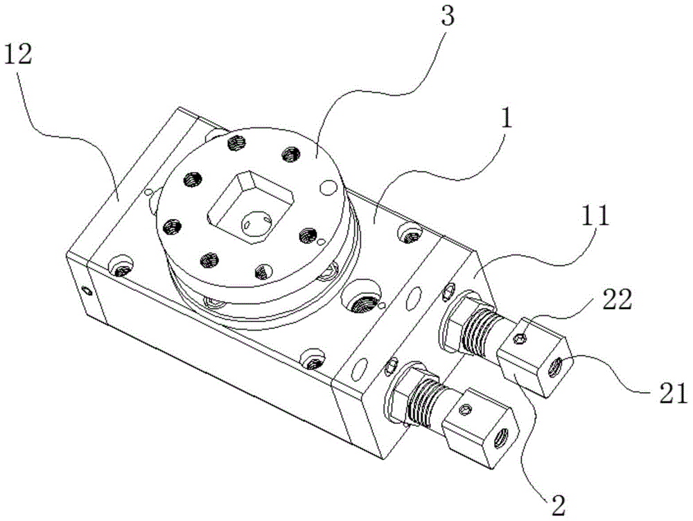
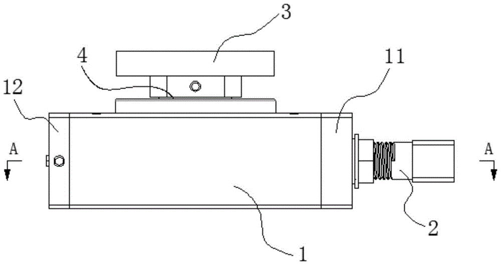
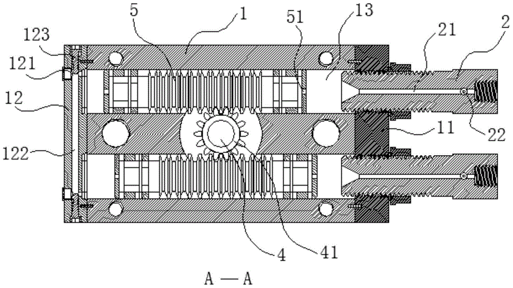
[0033] Such as Figure 1 to Figure 9 As shown, an example according to the specific implementation of the present invention is: a piston-type oscillating cylinder, which includes a cylinder body 1, an adjusting screw 2, a rotary disk 3, an output shaft 4, and a rack-shaped piston rod 5, wherein:

[0034] Such as Figure 1 to Figure 3 As shown, two cylinder chambers 13 are arranged side by side inside the cylinder body 1 ,...


PUM


Abstract

The invention discloses a piston type oscillating cylinder which comprises a cylinder body, rack-shaped piston rods, adjusting screw rods and an output shaft. The cylinder body is provided with two cylinder chambers and two end covers. The two rack-shaped piston rods are arranged in the two cylinder chambers respectively. The two adjusting screw rods are arranged on one end cover. The output shaft is fixedly provided with a gear which is in meshed connection with the two rack-shaped piston rods. The output shaft is connected with a rotary disk. The end cover where the adjusting screw rods are placed is a gas inlet end cover, and the other end cover is a gas outlet end cover. Each adjusting screw rod is provided with a gas inlet hole and a gas inlet adjusting mechanism. Each rack-shaped piston rod is provided with a vent hole. The gas outlet end cover is provided with two exhaust holes and two exhaust adjusting mechanisms which correspond to the two cylinder chambers respectively. According to the piston type oscillating cylinder, the rack-shaped piston rods are provided with the vent holes so that gas can flow to the other end from one end of each cylinder chamber, a buffer effect is achieved on the movement of the rack-shaped piston rods, the movement of the rack-shaped piston rods is stable and collision force is reduced.

Description

technical field [0001] The invention relates to the field of oscillating cylinders, in particular to a piston-type oscillating cylinder. Background technique [0002] Piston swing cylinder is a pneumatic actuator that uses the piston rod of one or two cylinders to drive the output shaft to make reciprocating rotary motion within a certain angle range. It is widely used in the indexing, flipping, sorting, clamping, valve The opening and closing of the robot and the arm movement of the robot, etc. The piston rod of the existing piston-type oscillating cylinder is cylindrical, and the piston rod of the cylinder is made into a rack shape by uniformly processing a number of teeth along the axial direction in the middle of the cylindrical surface of the piston rod. The rod rotates in mesh with a gear fixed on the output shaft to convert the linear motion of the piston rod of the cylinder into the rotation of the output shaft. After the cylinder is inhaled, the piston rod is dire...

Claims


Application Information

Patent Timeline
Patent Type & Authority Patents(China)
IPC IPC(8): F15B15/12F15B15/20
CPCF15B15/1423F15B15/22F15B2015/1495
Inventor 曾昭文卓雪艳曾盛绰其他发明人请求不公开姓名
Owner GUANGXI UNIV
Why Eureka
Eureka Blog
Learn More