

Pipe liquid filling bulging test method and device
A test method and pipe technology, applied in the direction of applying stable tension/pressure to test the strength of materials, can solve the problems of imperfect and unified test methods and devices
Inactive Publication Date: 2015-05-20
BEIHANG UNIV
View PDF8 Cites 13 Cited by
- Summary
- Abstract
- Description
- Claims
- Application Information
AI Technical Summary
Problems solved by technology
With the development of process application, researchers found that due to factors such as high-pressure uniform surface force and other factors, the material performance parameters obtained by the original plate uniaxial tensile test are not suitable for the analysis of the pipe liquid-filled forming process, and the actual production has a great influence on the material performance. The requirements are getting higher and higher, and the current testing methods and devices for the liquid-filled forming performance of pipes are not perfect and unified.
Method used
View moreImage
Smart ImageViewing Examples

Examples
specific Embodiment
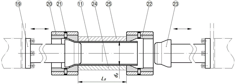
[0028] Material name and grade QSTE340TM, pipe diameter d 0 =72.5mm, wall thickness t 0 =3.8mm, pipe test section L 0 / d 0 = 2.0. The material parameters obtained by the bulging test are shown in Table 1 below, and the stress-strain curve is shown in Figure 6 shown.
[0029] Table 1
[0030]
Login to View More PUM
 Abstract
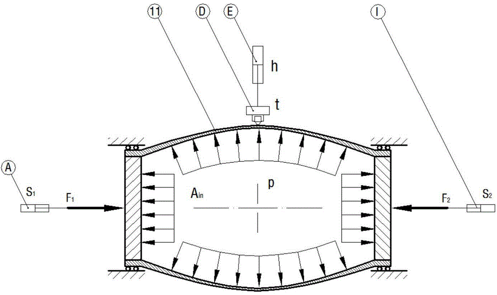
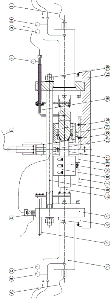
The invention discloses a pipe liquid filling bulging test method and device. The pipe liquid filling bulging test method comprises the following steps: restraining two ends of a test pipe, only releasing the freedom degree of axial movement of the test pipe, applying uniformly-increased hydraulic pressure p inside the test pipe, and synchronously applying equal force on the two ends of the pipe respectively until the pipe is broken; acquiring a real-time wall thickness t and a bulging height h of a highest point of the pipe in a bulging process; when the axial force can be used for rightly counteracting the acting force of internal pressure to the end surface of an inner cavity of the pipe, deducing an axial free bulging stress-strain curve and material parameters of the pipe by virtue of acquired bulging process data p, t and h according to a plastic theory. Pipe forming tests under different loading routes can be completed by applying different pulling force or pushing force at the two ends of the pipe so as to provide test data for the drawing of a pipe forming limit diagram. Embodiments show that a pipe bulging stress-strain curve and pipe stress-strain data with a relatively large strain range can be accurately acquired by using the method disclosed by the invention; and the test device and the pipe are convenient to disassemble and assemble repeatedly in expansion and bulging processes, and are good in implementation effect.
Description
technical field [0001] The invention belongs to the technical field of material performance testing, and in particular relates to a test method and device for testing the liquid-filled forming performance of pipes based on axial free bulging. Background technique [0002] Tube Hydroforming technology (Tube Hydroforming) refers to the high-pressure flexible forming process of hollow thin-walled parts with a certain complex shape, which is also called tube hydroforming. It is an internal high pressure forming or hydroforming process. In view of its particular suitability for forming integral, complex, thin-walled hollow parts, high forming precision, high material utilization rate, and low production cost, this technology has developed rapidly at the beginning of this century. , And began to be widely used in aerospace, automobile manufacturing and other industries. With the development of process application, researchers found that due to factors such as high-pressure unifor...
Claims
Login to View More Application Information
Patent Timeline
 IPC IPC(8): G01N3/12
Inventor郎利辉程鹏志谷姗姗
OwnerBEIHANG UNIV