electric motor

A technology for a motor and a main body, applied in the field of motors, can solve the problems of axial vibration and noise of components

Active Publication Date: 2018-04-13
SANKYO SEIKI MFG CO LTD +1
View PDF6 Cites 0 Cited by
  • Summary
  • Abstract
  • Description
  • Claims
  • Application Information

AI Technical Summary

Problems solved by technology

[0008] However, when the axial dimensions of the three stator cores, coil bobbins, and bottom plate arranged in the motor case are larger than the axial dimensions in the motor case (specifically, from the bottom surface of the motor case to the anti-output side of the end plate If the size of the surface of the motor is small, the components arranged in the motor case will vibrate in the axial direction
Therefore, there is a disadvantage that noise is generated due to axial (up and down) vibration between the stator core, coil bobbin, and base plate

Method used


Image

  • electric motor
  • electric motor
  • electric motor

Examples


Embodiment Construction

[0045] Hereinafter, a motor according to an embodiment of the present invention will be described in detail with reference to the drawings.

[0046] Also, in the following descriptions, the side where the output shaft of the motor is located (for example, figure 1 , Figure 2B , image 3 The upper side in ) is called "output side", and the side opposite to the above output side is called "anti-output side". In addition, in the following description, "the state before assembly" refers to the state when the components such as the motor body part and the reduction gear part are arranged in the motor case, but the end plate is not fixed to the upper end of the motor case. The "state" refers to a state in which components such as the motor main body and the reduction gear are arranged in the motor case, and the end plate is fixed to the upper end of the motor case.

[0047] (Schematic structure of the motor)

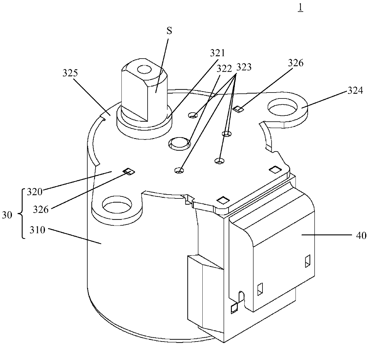
[0048] figure 1 It is a perspective view which shows the whole stru...


PUM


Abstract

A motor can prevent a component disposed within a housing composed of a motor shell and an end plate from axially vibrating in the housing and comprise a motor body, a reduction gear portion and the housing; the reduction gear portion reduces the power of the motor body and transmits the power; the housing accommodates the motor body and the reduction gear portion; the motor body comprises a rotor and a stator; the rotor comprises a spindle and a magnet for driving; the stator comprises a stator core and a bobbin; the reduction gear portion comprises a support plate which supports gears of a gear set to rotate; the motor body and the reduction gear portion are axially arranged; the face, opposite to the output side, of the support plate is provided with a butt protrusion protruding towards the output side; the butt portion is used for butting the end face, close to the output side, of the stator of the motor body; protruding quantity of the butt protrusion, opposite to the output side, allows the sum of axial size of the motor body and axial size of the reduction gear portion disposed with the housing to be greater than or equal to the axial size of the housing, before assembly.

Description

technical field [0001] The present invention relates to an electric motor, and more specifically, to an electric motor with a reducer. Background technique [0002] At present, there is known a motor with a reducer of the following structure, which includes: a stepping motor body; a gear reduction mechanism, which transmits the power of the stepping motor body after deceleration; The housing accommodates the stepping motor main body and the gear reduction mechanism; and an end plate fixed to the upper end of the motor housing to cover the upper end of the motor housing (for example, refer to Patent Document 1). [0003] In the motor described in Patent Document 1, the stator constituting the main body of the stepping motor includes three stator cores and two coil bobbins around which a driving coil is wound. The gear reduction mechanism includes a bottom plate abutting against an end surface of the stator, a support shaft fixed to the bottom plate, and a gear set composed o...

Claims


Application Information

Patent Timeline
Patent Type & Authority Patents(China)
IPC IPC(8): H02K7/116H02K37/24F16H57/025
CPCF16H57/025H02K7/116
Inventor 西村清志覃庆国伊藤敏朗
Owner SANKYO SEIKI MFG CO LTD
Why Eureka
Try Eureka