Method and system for locking offset point of light modulator

A technology of optical modulator and bias point, which is applied in the field of optical communication, can solve the problems such as the inability to track and lock, and achieve the effect of fast locking speed and high precision

Active Publication Date: 2015-05-20
HISILICON OPTOELECTRONICS CO LIMITED
View PDF7 Cites 10 Cited by
  • Summary
  • Abstract
  • Description
  • Claims
  • Application Information

AI Technical Summary

Problems solved by technology

[0004] In the bias point locking method of the above modulation process, it is realized based on the principle that when the bias point is exactly at the valley point (null) or peak point (peak) of the modulation signal, the light effects brought about by the positive and negative half cycles are equal and cancelled. Therefore, it can only achieve tracking locking when the bias point is located at a special point on the modulation curve, but it is still unable to perform tracking locking when the bias point is located at any other point on the curve

Method used


Image

  • Method and system for locking offset point of light modulator
  • Method and system for locking offset point of light modulator
  • Method and system for locking offset point of light modulator

Examples


Embodiment Construction

[0043] In order to make the purpose, technical solutions and advantages of the embodiments of the present invention clearer, the technical solutions in the embodiments of the present invention will be clearly and completely described below in conjunction with the drawings in the embodiments of the present invention. Obviously, the described embodiments It is a part of embodiments of the present invention, but not all embodiments. Based on the embodiments of the present invention, all other embodiments obtained by persons of ordinary skill in the art without creative efforts fall within the protection scope of the present invention.

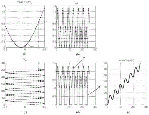
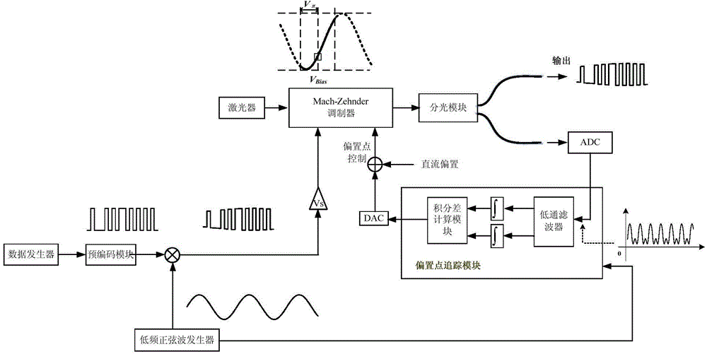
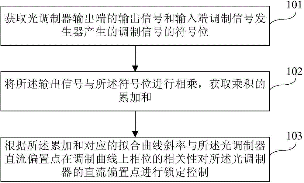
[0044] In the embodiment of the present invention, in order to enable tracking and locking when the DC bias point of the Mach-Zehnder optical modulator is located at any point on the modulation curve, it is necessary to find a one-to-one correspondence with the bias point on the modulation curve, Lock any point on the modulation curve through the ...


PUM


Abstract

An embodiment of the invention discloses a method and a system for locking an offset point of a light modulator. The method for locking the offset point of the light modulator comprises the following steps of acquiring outputting signals of an outputting end of the light modulator and sign bits of modulating signals generated by a modulating signal generator of an inputting end of the light modulator; multiplying the outputting signals and the sign bits and acquiring the cumulative sum of the arithmetic product; and performing locking control on a direct-current offset point of the light modulator according to fitting curve slope corresponding to the cumulative sum and phase correlation of the direct-current offset point of the light modulator on a modulating curve. According to the embodiment, the offset point can be tracked and locked no matter where the offset point is positioned on the modulating curve.

Description

technical field [0001] The invention relates to optical communication technology, in particular to a method and system for locking a bias point of an optical modulator. Background technique [0002] With the development of optical communication technology, more and more large data volumes are transmitted through optical communication. In optical communication, the optical modulator is the control part of the optical device, and its control performance largely determines the performance of the transmission optical module. The modulation curve of the optical modulator is a sine wave curve, and different modulation patterns can be obtained by biasing the data signal at different points of the modulation curve. Because the optical device is affected by its own aging, external environment temperature and pressure, etc., the modulation curve will drift randomly, resulting in a decrease in modulation quality and affecting service performance. Therefore, the fixed position of the ...

Claims


Application Information

Patent Timeline
Patent Type & Authority Applications(China)
IPC IPC(8): H04B10/516
Inventor 李雁飞徐川
Owner HISILICON OPTOELECTRONICS CO LIMITED
Why Eureka
Try Eureka