Positive and reverse spiral amplitude chip mounting head for chip mounting machine and amplitude change method of positive and reverse spiral amplitude chip mounting head

A patch head and helical technology, which is applied to the forward and reverse helical luffing patch head of the placement machine and its luffing field, can solve the problems of equal nozzle spacing and can be automatically adjusted, and achieves simple structure and improved performance. Reliable performance and action

Inactive Publication Date: 2015-05-20
CENTRAL SOUTH UNIVERSITY OF FORESTRY AND TECHNOLOGY
View PDF6 Cites 7 Cited by
  • Summary
  • Abstract
  • Description
  • Claims
  • Application Information

AI Technical Summary

Problems solved by technology

[0009] Although the above-mentioned patents all relate to the placement head of the placement machine, none of them solve the problem. Patent CN201320364205 relates to the equal and automatic adjustment of the internal nozzle spacing of the placement head, but careful analysis shows that this patent still simply describes " The vertical servo motor drives the vertical moving bracket to drive the nozzles to move back and forth on the trapezoidal plate, and the nozzle support beam keeps all the nozzles on the same horizontal straight line, so that the distance between the nozzles is always equal and automatically adjusted

Method used


Image

  • Positive and reverse spiral amplitude chip mounting head for chip mounting machine and amplitude change method of positive and reverse spiral amplitude chip mounting head
  • Positive and reverse spiral amplitude chip mounting head for chip mounting machine and amplitude change method of positive and reverse spiral amplitude chip mounting head
  • Positive and reverse spiral amplitude chip mounting head for chip mounting machine and amplitude change method of positive and reverse spiral amplitude chip mounting head

Examples


Embodiment 1

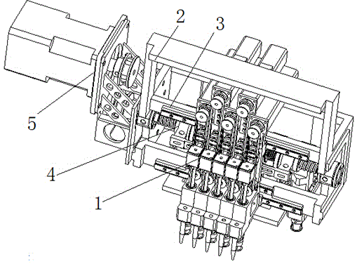
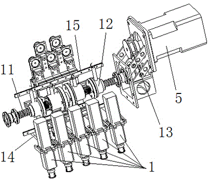
[0031] attached Figure 1-4 A technical embodiment of the present invention is given. It can be seen from the drawings that the present invention relates to a forward and reverse spiral amplitude mounter head, which includes more than two patch suction nozzles 1, and multiple patch suction nozzles 1 are arranged in parallel and combined together. Installed on the patch head bracket 2, and can slide along the p-axis linear guide rail 3, it is characterized in that a luffing mechanism 4 is also installed on the patch head bracket 2, and the luffing mechanism is connected with each patch suction nozzle assembly Together, the multiple patch suction nozzles 1 are driven by the luffing mechanism 4 installed on the patch head bracket 2 to slide along the p-axis linear guide rail 3, and are driven by the servo motor 5 through the luffing mechanism 4. Amplitude adjustment movement.

[0032] Further, among them, No. 3 suction nozzle assembly 6 is in the middle position, fixed on the p...


PUM


Abstract

The invention provides a positive and reverse spiral amplitude chip mounting head of a chip mounting machine and an amplitude change method of the positive and reverse spiral amplitude chip mounting head. The positive and reverse spiral amplitude chip mounting head comprises more than two chip mounting suction nozzle assemblies, wherein the plurality of chip patching nozzle assemblies are arranged in parallel and combined together, are arranged on a chip mounting head support frame, and can slide along a p-axis linear guide rail. The chip mounting head is characterized in that an amplitude change mechanism is also arranged on the chip mounting support frame, the amplitude change mechanism is connected with each movable chip mounting suction nozzle assembly, the patch suction nozzle assemblies are driven by the amplitude change mechanism arranged on the chip mounting head support frame to slide along the p-axis linear guide rail, and are driven by a servo motor to do amplitude change regulation movement through the amplitude change mechanism, and in addition, an identical space between suction nozzles arranged on each chip mounting suction nozzle assembly is always maintained in the amplitude change process.

Description

technical field [0001] The invention belongs to a component operation method and device for manufacturing and processing equipment of electronic devices, in particular to a placement head and a placement method of a placement machine for mounting small electronic devices, which are mainly used for high-speed, stable and accurate mounting on a pcb board mount small electronic components. It realizes the fully automatic control from pcb board feeding, board feeding, positioning, placement head suction, positioning, and placement. Background technique [0002] The placement machine is also called "mounting machine" and "Surface Mount System". In the production line, it is arranged after the dispensing machine or screen printing machine. A device that accurately places a device on a PCB pad. The placement head is the direct mechanism for the placement machine to carry out the placement work. It is one of the key technologies of the placement machine. After picking up the compo...

Claims


Application Information

Patent Timeline
Patent Type & Authority Applications(China)
IPC IPC(8): H05K3/30
CPCH05K3/303
Inventor 高自成李立君肖军信龙新元
Owner CENTRAL SOUTH UNIVERSITY OF FORESTRY AND TECHNOLOGY
Why Eureka
Try Eureka