Forage laying and airing device for animal husbandry

A technology of animal husbandry and forage, which is applied in the field of animal husbandry, which can solve the problems that the forage cannot be spread evenly at equal distances, and it is unfavorable for the forage to spread and dry, so as to improve the effect of spread and spread, improve the effect and reduce the accumulation effect

Pending Publication Date: 2019-04-19
钱巍
View PDF7 Cites 1 Cited by
  • Summary
  • Abstract
  • Description
  • Claims
  • Application Information

AI Technical Summary

Problems solved by technology

But it also has the obvious disadvantage that the forage cannot be evenly sprinkled on the ground after being thrown out, which often causes the forage thrown back and forth to be pressed together, which is not conducive to the spreading of the forage

Method used


Image

  • Forage laying and airing device for animal husbandry
  • Forage laying and airing device for animal husbandry
  • Forage laying and airing device for animal husbandry

Examples


Embodiment 1

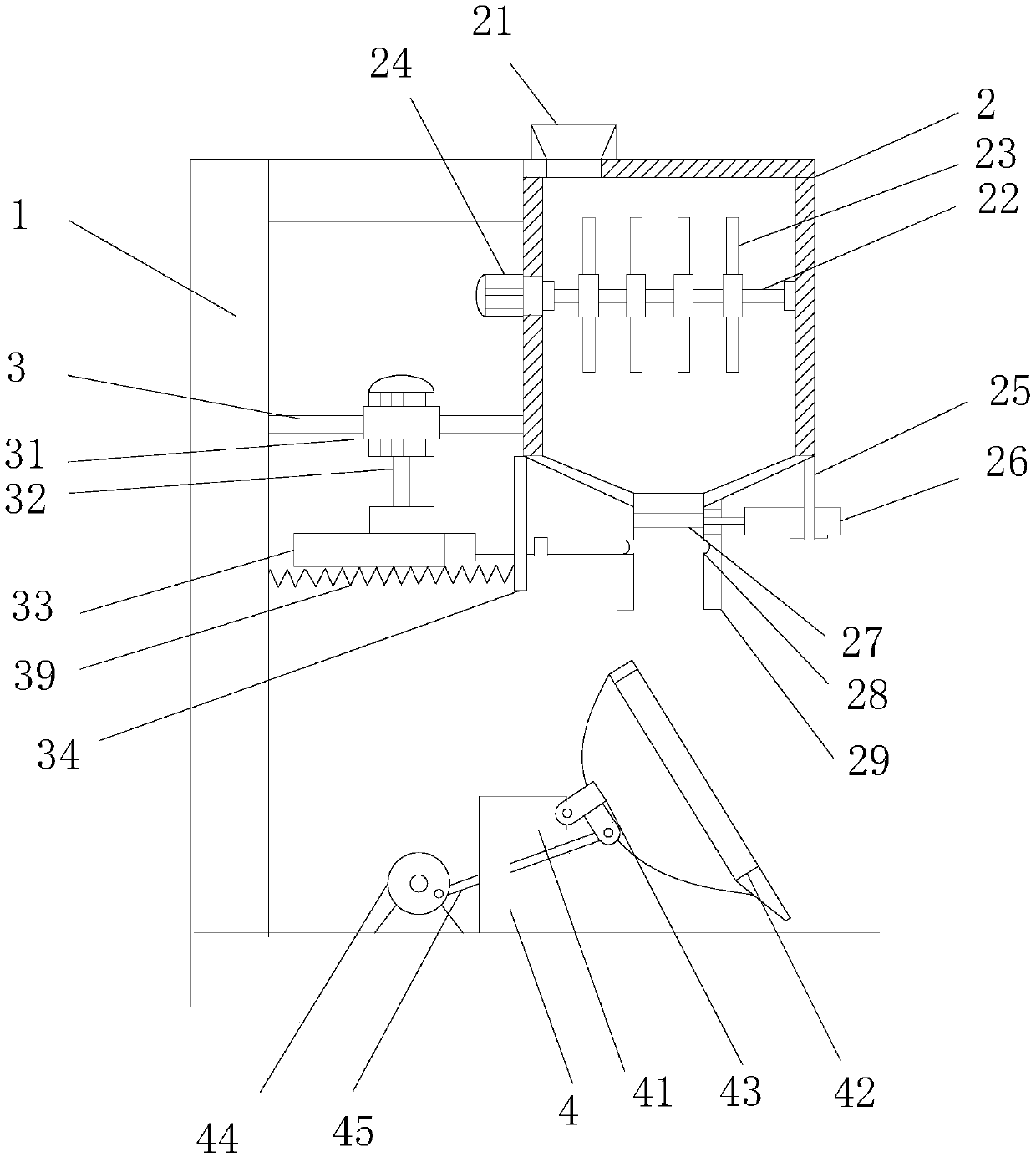
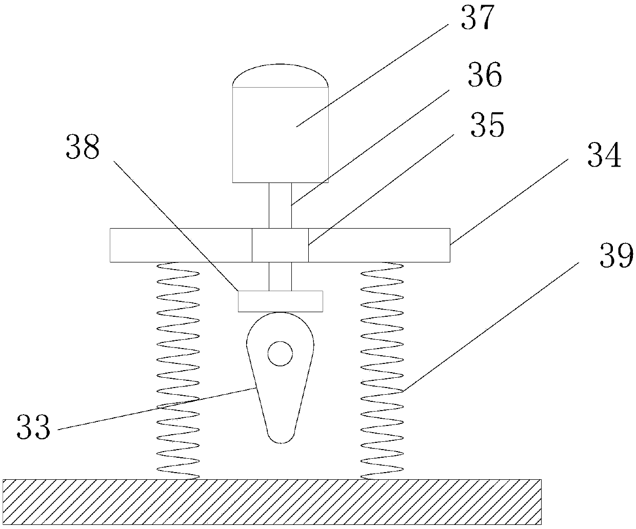
[0023] see figure 1 , a kind of forage spreading and drying device for animal husbandry, comprising a frame 1, a material barrel 2 is installed on the top of the frame 1, a throwing rack 4 is installed on the bottom of the frame 1, and the top of the material barrel 2 A receiving hopper 21 is installed, the bottom of the material barrel 2 is provided with a discharge port 29, a fixed plate 25 is installed on the side wall of the material barrel 2, and a cylinder 26 is installed on the fixed plate 25. The upper end of the feed port 29 is equipped with a discharge valve 27, the valve plug of the discharge valve 27 is connected with the telescopic rod at the driving end of the cylinder 26, and the drive frame 3 is installed between the frame 1 and the material barrel 2, the Drive motor 31 is installed on the drive frame 3, and the driving end of described drive motor 31 is equipped with drive cam 33 through drive shaft 32, and limit plate 34 is set synchronously on described driv...

Embodiment 2

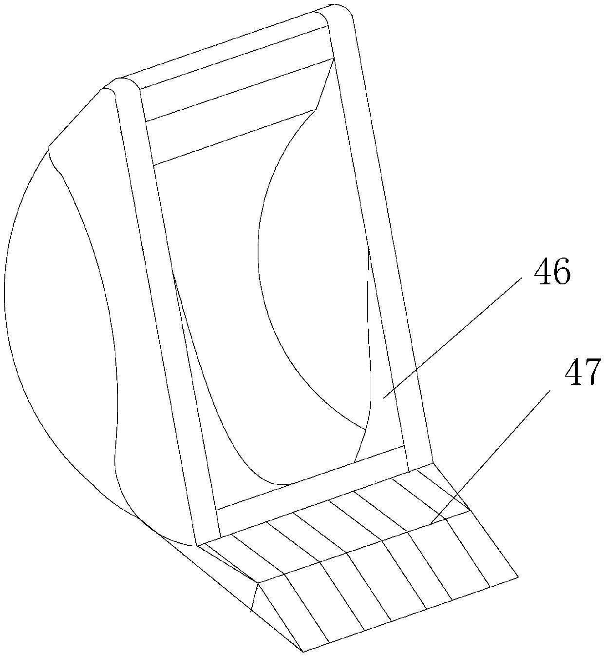
[0028] see image 3 , this embodiment is a further optimization of Embodiment 1. On the basis of it, a deflector 47 is installed on the lower edge of the mouth of the throwing hopper 42, and the deflector 47 has the effect of extending the force-bearing surface, so that The material is thrown farther, and if you need to spread it at a close distance, you can choose to disassemble it; the left and right sides of the mouth of the throwing hopper 42 are equipped with baffles 46 to prevent the material from spilling to both sides when throwing the material, thereby avoiding front and rear. The thrown material produces an intersection.

[0029] Example scattered:

[0030] see figure 1 , this embodiment is further optimized as Embodiment 1. On the basis of it, a stirring shaft 22 is installed horizontally in the material barrel 2, and several beat rollers 23 are equidistantly installed on the stirring shaft 22. The material A stirring motor 24 is installed on the side wall of the...


PUM


Abstract

The invention relates to the field of the animal husbandry, in particular to a forage laying and airing device for the animal husbandry. The forage laying and airing device for the animal husbandry comprises a rack, wherein a material barrel is mounted on the top of the rack; a discharging opening is formed in the bottom end of the material barrel; a driving rack is mounted between the rack and the material rack; a driving motor is mounted on the driving rack; a transmission cam is mounted at the driving end of the driving motor through a driving shaft; the driving rack is synchronously provided with a limiting plate; a locking sleeve is mounted in the middle of the limiting plate; a push rod is mounted in the locking sleeve; an extrusion plate is mounted at the rear end of the push rod; astopping plate is mounted at the front end of the push rod; the transmission cam is attached to the extrusion plate; and a clamping groove is formed in the lower end of the discharging opening. By cooperation of cam transmission and an elastic resetting mechanism, gap type discharging is implemented, materials are laid and scattered on a foundation in small piles, it ensures that the distances among the different piles of materials are equal, and the laying and airing effect is improved.

Description

technical field [0001] The invention relates to the field of animal husbandry, in particular to a forage spreading and drying device for animal husbandry. Background technique [0002] In modern animal husbandry, it is usually necessary to plant a large amount of forage for livestock, and it is necessary to cut down a large amount of forage during the harvest season, expose it to the sun, and collect and store it after drying, so as to feed livestock in winter. Because the forage of the pasture is usually planted with a high density, after the grass is cut down, the thickness of the forage layer formed by the forage is very thick, which is not convenient for sun exposure. Therefore, in order to make the forage evenly exposed to the sun, increase the drying speed, make the forage more resistant to storage, and improve the quality of the stored forage, it is necessary to spread the forage layer more evenly. [0003] Chinese patent (authorized announcement number: CN103975699B...

Claims


Application Information

Patent Timeline
Patent Type & Authority Applications(China)
IPC IPC(8): A01D84/00A01D85/00
CPCA01D84/00A01D85/001
Inventor 钱巍
Owner 钱巍
Why Eureka
Try Eureka