
Pipe auxiliary supporting jig for machine tool and machine tool

An auxiliary support and machine tool technology, applied in the direction of support, manufacturing tools, metal processing machinery parts, etc., can solve the problems affecting machining accuracy and quality, pipe disturbance deformation, etc., to achieve stable and reliable processing, reduce disturbance deformation, avoid disturbance The effect of pipe dents

Pending Publication Date: 2020-06-26
KUNSHAN YUNCO PRECISION IND TECH
View PDF0 Cites 1 Cited by
  • Summary
  • Abstract
  • Description
  • Claims
  • Application Information

AI Technical Summary

Problems solved by technology

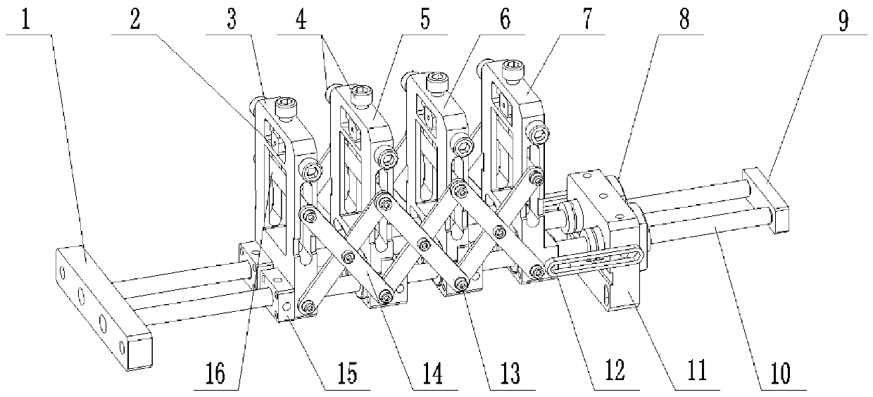
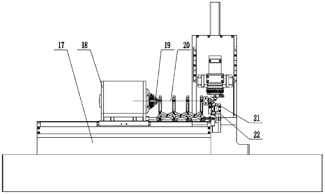
[0004] Aiming at the deficiencies of the prior art, the present invention provides a pipe auxiliary support jig for machine tools and a machine tool. The invention adopts a modular design, so that the support length of the pipe auxiliary support jig for machine tools can be increased or decreased arbitrarily according to the length of the pipe and the machine tool. And it makes the pipe auxiliary support jig for the machine tool move synchronously with the clamping rotation axis of the machine tool, avoiding the disturbance and deformation of the pipe due to insufficient rigidity during the processing, which affects the processing accuracy and quality

Method used


Image

  • Pipe auxiliary supporting jig for machine tool and machine tool
  • Pipe auxiliary supporting jig for machine tool and machine tool

Examples


Embodiment Construction

[0037] In order to make the purpose and technical solutions of the embodiments of the present invention more clear, the technical solutions of the embodiments of the present invention will be clearly and completely described below in conjunction with the drawings of the embodiments of the present invention. Apparently, the described embodiments are some, not all, embodiments of the present invention. Based on the described embodiments of the present invention, all other embodiments obtained by persons of ordinary skill in the art without creative efforts shall fall within the protection scope of the present invention.

[0038] Those skilled in the art can understand that, unless otherwise defined, all terms (including technical terms and scientific terms) used herein have the same meaning as commonly understood by those of ordinary skill in the art to which this invention belongs. It should also be understood that terms such as those defined in commonly used dictionaries shoul...


PUM


Abstract

The invention discloses a pipe auxiliary supporting jig for a machine tool and the machine tool. Various sliding blocks are fixed through cooperation of a rotating shaft end fixed plate, a limit stop,guide shafts, linear bearings, an X-axis end fixed plate and a sliding block fixing seat, the sliding blocks can be arranged between a collet chuck and a bush of the machine tool along the guide shafts, so that lifting and supporting are provided for the middle of a workpiece through supporting shaft sleeves at the tops of the sliding blocks. By means of the pipe auxiliary supporting jig for themachine tool and the machine tool, it can be ensured that the workpiece can be firmly clamped in the process that the machine tool machines precise thin-walled pipes with the outer diameter being 1 mmor below, the workpiece is precisely located, and machining to the workpiece is more stable and reliable. Through lifting to the supporting shaft sleeves and the sliding blocks, the conventional problems of pipe concaving and butt joint dislocation happening during locating and clamping and continuous machining to the workpiece can be avoided. Machining of precise thin-walled pipes with the outerdiameter being 1 mm or below can be achieved, and certain reference is provided for machining of other similar fine rotary parts.

Description

technical field [0001] The invention relates to the field of laser processing equipment, in particular to a pipe auxiliary support jig for a machine tool and a machine tool. Background technique [0002] As a precision professional tool used by CNC machine tools to control the position and movement of workpieces, clamping fixtures are designed and processed directly to determine the quality of their processed workpieces. With the rapid development of Industry 4.0 technology, the processing requirements and production requirements for precision parts, especially for low-rigidity and high-flexibility thin-walled tubular parts are gradually increasing. The conventional clamping support method and processing technology can no longer meet the clamping and processing of small workpieces such as precision thin-walled tubes with an outer diameter of 1mm or less. The field of ultramicromachining technology has increasingly become the focus and difficulty of research in the field of ...

Claims


Application Information

Patent Timeline
Patent Type & Authority Applications(China)
IPC IPC(8): B23Q3/06B23Q3/00B23Q7/00
CPCB23Q3/064B23Q3/00B23Q7/00
Inventor 胡罡夏发平
Owner KUNSHAN YUNCO PRECISION IND TECH
Learn More