
Air-cooled thermoelectric power generation apparatus and solar thermal power generation apparatus using air-cooled thermoelectric power generation apparatus

A technology for thermal power generation and thermoelectric power generation, which is applied in the direction of using solar energy to generate mechanical power, solar thermal power generation, generators/motors, etc. Effect

Inactive Publication Date: 2015-05-20
BMT LIMITED +1
View PDF4 Cites 0 Cited by
  • Summary
  • Abstract
  • Description
  • Claims
  • Application Information

AI Technical Summary

Problems solved by technology

On the other hand, in dish-type solar thermal power generation, the solar thermal power generation device can be miniaturized compared with tower-type solar thermal power generation and trough-type solar thermal power generation devices, but it is necessary to set the reflector in a parabolic shape, etc. limits of existence
In addition, if the sun is not out, power generation cannot be performed, and it also has the same disadvantages as solar photovoltaic power generation.

Method used


Image

  • Air-cooled thermoelectric power generation apparatus and solar thermal power generation apparatus using air-cooled thermoelectric power generation apparatus
  • Air-cooled thermoelectric power generation apparatus and solar thermal power generation apparatus using air-cooled thermoelectric power generation apparatus
  • Air-cooled thermoelectric power generation apparatus and solar thermal power generation apparatus using air-cooled thermoelectric power generation apparatus

Examples


Embodiment 1

[0084] Hereinafter, specific examples will be further described. In the following description, the case where solar thermal energy is used is demonstrated as a method of heating a heat medium, However, As mentioned above, it is not limited to this.

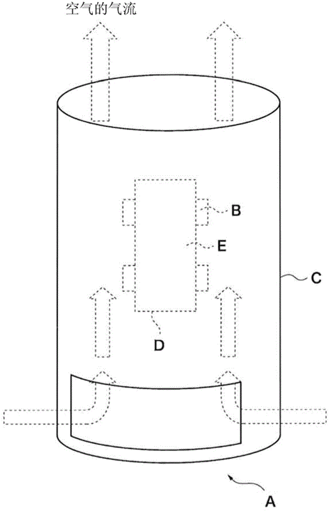
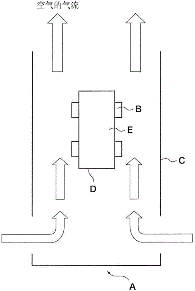
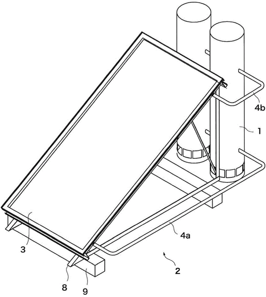
[0085] A case where the air-cooled thermoelectric power generation device 1 of the present invention is used as the solar thermal power generation device 2 will be described. The solar thermal power generation device 2 heats the heat medium by collecting heat from the sun's light energy by the solar thermal heat collection device 3 , and generates power by using the temperature difference between the two surfaces of the thermoelectric power generation element.

[0086]Since the solar thermal power generation device 2 has a plurality of embodiments depending on the configuration of each device, each embodiment will be described below. In addition, the solar thermal power generation device 2 is not limited to each of the following ...

Embodiment 2

[0124] Another example of the solar thermal power generation device 2 will be described. In Embodiment 1, the shape of the flow tube 120 is a square prism, but in this embodiment, the case where the shape of the flow tube 120' is a hexagonal prism will be described. In this case, a vertical cross-sectional view showing the vicinity of the upper part of the air-cooled thermoelectric power generation device 1' is shown in Figure 13 middle. Additionally, the Figure 13 The cross-sectional view of the β-β line is shown in Figure 14 middle. Additionally, the Figure 14 The longitudinal sectional view of the γ-γ line is shown in Figure 15 middle.

[0125] The air-cooled thermoelectric generating unit 12' in this embodiment includes a flow tube 120', a thermoelectric generating element 121, heat insulating materials 122, 123, and a cooling plate 126'. In addition, the description of parts having the same configuration as that of the air-cooled thermoelectric power generatio...

Embodiment 3

[0136] In the air-cooled thermoelectric generator 1 described above, natural air cooling is used, but for example, a cooling electric fan 128 may be provided below the air-cooled thermoelectric generator 12 to flow air from below to above. A longitudinal sectional view of the casing 11 in this case is shown in Figure 16 middle. In addition, since air can flow from above to below even when the cooling electric fan 128 is provided, the cooling electric fan 128 may be provided above the thermoelectric generation unit 12 .

[0137] In addition, instead of installing an electric cooling fan in each air-cooled thermoelectric generation unit 12 , an electric cooling fan 128 may be provided below or above the housing 11 to generate air flow inside the housing 11 .

[0138] With such a configuration, the cooling effect of the cooling fins 126 and 126' can be enhanced, so that the temperature difference of the thermoelectric power generation element 121 can be increased, leading to an...


PUM


Abstract

The purpose of the present invention is to provide an air-cooled thermoelectric power generation apparatus and a solar thermal power generation apparatus using the air-cooled thermoelectric power generation apparatus. This solar thermal power generation apparatus is provided with a solar heat collecting apparatus that heats a heat medium by means of solar light irradiation, an air-cooled thermoelectric power generation apparatus, and a heat medium transfer pipe that transfers the heat medium thus heated. The air-cooled thermoelectric power generation apparatus has a housing that is provided with an air inlet for taking in air, and an air-cooled thermoelectric power generation unit that generates power using heat of the heat medium. The air-cooled thermoelectric power generation unit is provided with a thermoelectric power generation element that generates power by means of a temperature difference, and a heat sink that dissipates heat from the thermoelectric power generation element. A temperature of a discretionary surface of the thermoelectric power generation element is increased by means of the heated heat medium, and a temperature of a thermoelectric power generation element surface, which is different from the heated surface of the thermoelectric power generation element, is reduced to be lower than the temperature of the heated surface by means of the heat sink and the air taken in from the air inlet, thereby generating power by means of the thermoelectric power generation element.

Description

technical field [0001] The present invention relates to an air-cooled thermoelectric power generation device and a solar thermal power generation device using the air-cooled thermoelectric power generation device. Background technique [0002] Power generation utilizing natural energy has drawn attention due to increased awareness of environmental protection. As power generation utilizing natural energy, solar photovoltaic power generation, solar thermal power generation, geothermal power generation, wave power generation, and the like are known. However, most of these power generation methods require large-scale devices, and only photovoltaic power generation devices are the only ones that are miniaturized and widely used in households. [0003] However, in the case of photovoltaic power generation, there are disadvantages such as being unable to generate electricity at night. For this reason, there is a demand for a power generating device using natural energy that can b...

Claims


Application Information

Patent Timeline
IPC IPC(8): H02N11/00
CPCH10N10/13Y02E10/46F03G6/04
Inventor 守谷成人
Owner BMT LIMITED
Learn More