
Roller replacement device

A roll changing device and roll technology, applied in the direction of metal rolling, metal rolling racks, manufacturing tools, etc., can solve the problems of disassembly and reassembly, etc.

Active Publication Date: 2015-05-27
HEFEI BAISHENG SCI & TECH
View PDF7 Cites 3 Cited by
  • Summary
  • Abstract
  • Description
  • Claims
  • Application Information

AI Technical Summary

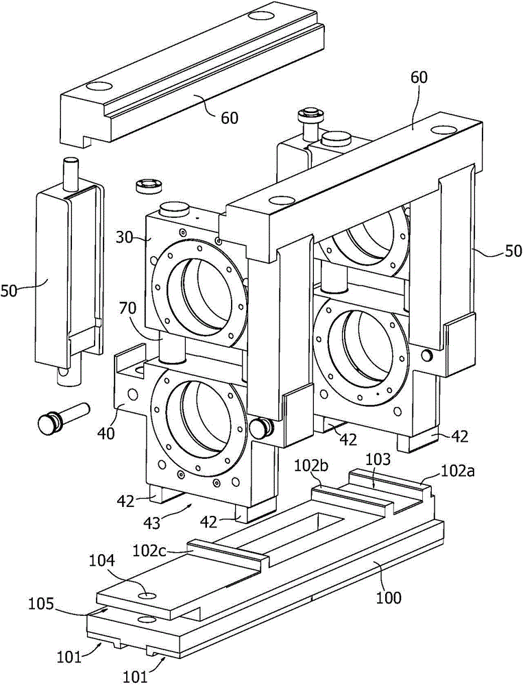
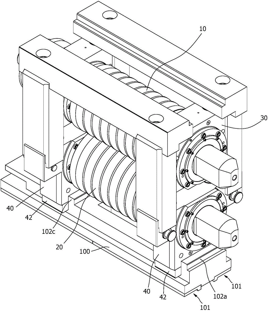
Problems solved by technology

However, the roll systems in the prior art are all separated from each other by the upper and lower roll bearing housings, and the lower end of the column is designed to be hinged with the base. Although it is convenient to take and place the roll system, it is still necessary to release the upper beam against the column. The fixed constraints of this kind of disassembly and reassembly process are also very complicated.

Method used


Image

  • Roller replacement device
  • Roller replacement device

Examples


Embodiment Construction

[0010] For the convenience of explanation and understanding, some basic orientation and position concepts are explained and defined first.

[0011] The power side or end of the rolling mill or roll refers to the side where the shaft end of the roll is connected to the power shaft, and the opposite side or end is the operating side or end; the incoming or incoming side of the roll refers to the side where the material to be rolled begins to enter the roll The rolling side, the discharge side of the roll refers to the side where the material to be rolled leaves the roll after being rolled; the up and down directions refer to the state where the roll is placed horizontally, and the following description only takes this state as an example. . The rolling mill can also be placed in a vertical roll manner for rolling.

[0012] see figure 1 , 2 , the roll changing device includes a slide plate 100, the slide plate 100 is provided with a limit portion to cooperate with the lower en...


PUM


Abstract

The invention relates to a roller replacement device, which comprises a sliding plate, wherein limiting parts matched with the lower end faces of lower bearing pedestals connected with the two ends of a lower roller are arranged on the sliding plate, and are used for limiting the displacement of the sliding plate and the lower bearing pedestals along the axial direction of the rollers and parallel to the advancing direction of a material; the sliding plate forms guide sliding fit with guide rails on a base of a rolling mill. According to the roller replacement device, the degrees of freedom of the sliding plate and the lower bearing pedestals along the axial direction of the rollers and in the advancing direction of the material are restricted by the limiting parts on the sliding plate, and the lower bearing pedestals are arranged on the sliding plate, so that the lower bearing pedestals are probably not required to move downwards, and the rollers move together with the sliding plate in a movement process of the sliding plate, and can be conveniently pushed into and pulled out of a rack of the rolling mill.

Description

technical field [0001] The invention relates to steel rolling equipment, in particular to a roll changing device of a rolling mill. Background technique [0002] The processing of the centerline bar in the prior art mostly adopts rolling mill to form. The rolling mill can generally be divided into archway frame, cantilever frame or archway frame welded by profiles in terms of its structure. The upper and lower rolls form a roll system to roll the material to be rolled. Because the lower bearing housings are all fixed on the bottom support of the archway type frame by bolts, the pressing device of the upper bearing housing is usually arranged on the upper beam, that is to say, the upper and lower rolls are arranged independently of each other. When replacing the rolls, not only is it time-consuming and labor-intensive to replace the rolls, but also the roll system needs to be repositioned, adjusted, and locked. [0003] The applicant once disclosed the design scheme of rele...

Claims


Application Information

Patent Timeline
Patent Type & Authority Applications(China)
IPC IPC(8): B21B31/10
Inventor 熊化平娄霆陈磊申晓庆
Owner HEFEI BAISHENG SCI & TECH
Learn More