Axial pressing locking device

A locking device, axial technology, applied in the direction of grinding workpiece support, etc., to achieve the effect of convenient use, firm and reliable fixation

Active Publication Date: 2015-05-27
深圳市佳易研磨有限公司
View PDF6 Cites 2 Cited by
  • Summary
  • Abstract
  • Description
  • Claims
  • Application Information

AI Technical Summary

Problems solved by technology

However, since the shaft and cylinder of the hanger need to rotate during work, the clamp must meet the requirements of firm clamping without loosening and easy adjustment. However, there is no such product yet.

Method used


Image

  • Axial pressing locking device
  • Axial pressing locking device
  • Axial pressing locking device

Examples


Embodiment 1

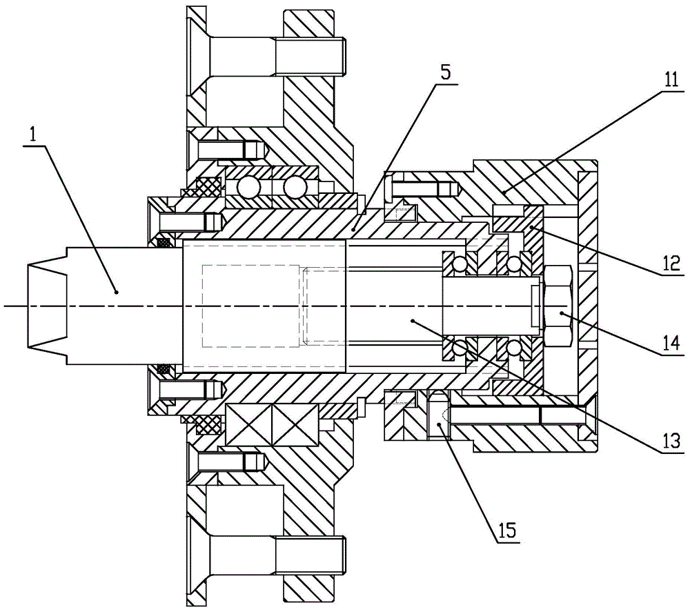
[0040]In this embodiment, the rotating part adopts the rotating shaft 13 , and the anti-rotation adjusting part adopts an assembly composed of a rotating handle 11 , an anti-rotation ring 12 and a ball screw 15 .

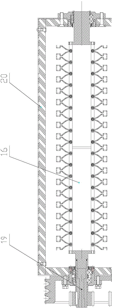
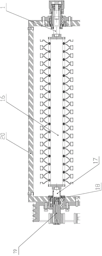
[0041] The specific structure is as image 3 As shown, the axial compression locking device includes a compression shaft 1 and a compression sleeve 5, one end of the compression shaft 1 is inserted into the sliding cavity of the compression sleeve 5, and the compression shaft 1 and the compression sleeve 5 sliding cavity The cross-section of the shaft adopts a square cross-section or adopts anti-rotation shapes such as splines, so that the compression shaft 1 can only slide axially in the compression sleeve 5 and cannot rotate, so as to transmit torque. In the compression shaft sleeve 5, a rotating shaft 13 is also installed by bearings. The installation requirements of the rotation shaft 13 can only be rotated in the compression shaft sleeve 5 without axial displac...

Embodiment 2

[0044] Such as Figure 4 As shown, in the axial compression locking device in this embodiment, the rotating part adopts the nut 2 , and the anti-rotation adjusting part also adopts a structure different from that in the first embodiment, mainly the inner and outer spline sleeves 3 . The specific structure is described as follows: the axial compression locking device includes a compression shaft 1 and a compression sleeve 5. Similarly, one end of the compression shaft 1 is inserted into the sliding cavity of the compression sleeve 5, and the compression shaft 1 and the compression sleeve 5 The cross section of the sliding cavity adopts a square cross section or anti-rotation shape such as a spline, so that the compression shaft 1 can only slide axially in the compression sleeve 5 and cannot rotate, so as to transmit torque. The right end of the pressing shaft 1 is provided with an external thread to form a screw rod, and the nut 2 as a rotating part is installed on the screw ro...


PUM


Abstract

The invention discloses an axial pressing locking device, which comprises a pressing shaft (1) and a pressing shaft sleeve (5), wherein one end of the pressing shaft (1) is inserted into a sliding cavity of the pressing shaft sleeve (5), the cross section of a sliding cavity of the pressing shaft (1) and the pressing shaft sleeve (5) adopts an anti-rotation shape, a rotating element is also arranged on the pressing shaft sleeve (5), the rotating element and the pressing shaft (1) are coaxial and are connected through screw threads, and an anti-rotation regulating element is also arranged between the pressing shaft sleeve (5) and the rotation element so that the pressing shaft sleeve (5) and the rotating element are locked after the rotating element is regulated to a proper position. The axial pressing locking device has the advantages that the firm positioning of the regulation of the pressing shaft (1) can be conveniently realized, the structure is relatively simple, the use is convenient, the installation of components is convenient, and a hanging tool can be precisely positioned.

Description

technical field [0001] The invention relates to an axial compression locking device, in particular to a device capable of positioning a shaft or a workpiece through axial compression installation. Background technique [0002] In the field of machinery, there are often requirements for fastening and fixing workpieces, mechanical parts or shafts, especially in some cases not only to achieve axial tightening, but also to transmit torque, and to achieve fast loading and unloading Require. For example, when grinding and polishing some high-value-added products such as jewelry and watches, suspension polishing is generally used. This polishing mode can effectively polish the products, and can avoid collisions of products and reduce unnecessary losses. [0003] figure 1 It is a schematic diagram of a grinding and polishing machine currently on the market, that is, the hanger is fixed on the hanger shaft 16 of the machine. This is mainly for the stability of the hanger and to ens...

Claims


Application Information

Patent Timeline
Patent Type & Authority Applications(China)
IPC IPC(8): B24B41/06
CPCB24B41/061
Inventor 蔡绍华
Owner 深圳市佳易研磨有限公司
Why Eureka
Try Eureka