Stacker for clay laths

A bar palletizing machine and frame technology, which is applied in the field of mud bar production, can solve the problems of large space occupation, high labor intensity, and low stacking speed, and achieve the effect of neat stacking and increased stacking speed

Inactive Publication Date: 2015-05-27
HUNAN SLON EQUIP
View PDF13 Cites 18 Cited by
  • Summary
  • Abstract
  • Description
  • Claims
  • Application Information

AI Technical Summary

Problems solved by technology

[0002] At present, the mud strips produced by the mud cutter generally need to be palletized. At present, manual palletizing is commonly used to realize palletizing, and there are also palletizing machines with a relatively high degree of automation. The cost of manual palletizing is low, but the labor intensity is high. , the palletizing speed is low, and the operation safety is low. The current palletizing machine is a large frame structure, which occupies a large space, is difficult to transport and place, and the structure is relatively complicated, and the palletizing efficiency is not high.

Method used


Image

  • Stacker for clay laths
  • Stacker for clay laths
  • Stacker for clay laths

Examples


Embodiment Construction

[0031] In order to make the content of the present invention more clearly understood, the present invention will be further described in detail below based on specific embodiments and in conjunction with the accompanying drawings.

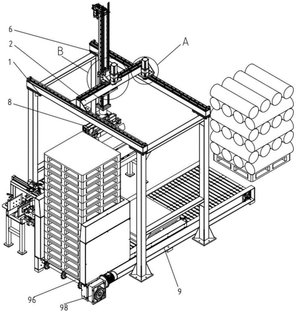
[0032] Such as Figure 1-7 Shown, a kind of mud bar palletizer, it comprises:

[0033] Rack 1;

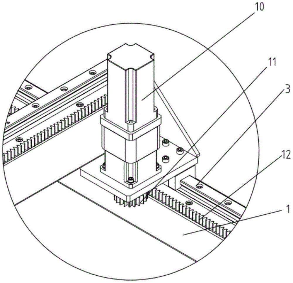
[0034] The X-direction longitudinal beam 2, the X-direction longitudinal beam 2 is movably installed on the frame 1 through the first guide rail slider pair 3;

[0035] The X-direction moving device is arranged between the X-direction beam 2 and the frame 1 so that it is used to drive the X-direction beam 2 to move on the frame 1;

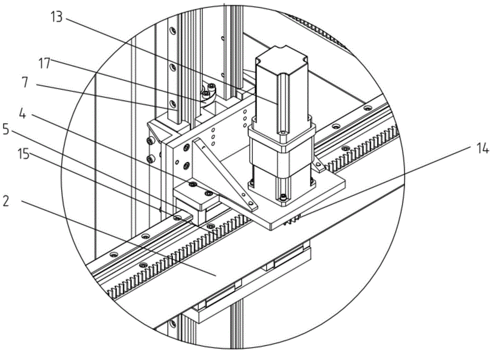
[0036] The Y-direction moving seat 4, the Y-direction moving seat 4 is movably installed on the X-direction longitudinal beam 2 through the second guide rail slider pair 5;

[0037] Y direction moving device, Y direction moving device is arranged between Y direction moving seat 4 and X direction longitudinal beam 2 so tha...


PUM


Abstract

The invention discloses a stacker for a clay lath. The stacker comprises a frame, an X-direction carling, an X-direction moving device, a Y-direction moving seat, a Y-direction moving device, a Z-direction moving beam, a Z-direction moving device, a gripping apparatus and a transportation support device, wherein the X-direction carling is movably arranged on the frame through a first guide rail slider pair; the X-direction moving device is arranged between the X-direction carling and the frame; the Y-direction moving seat is movably arranged on the X-direction carling through a second guide rail slider pair; the Y-direction moving device is arranged between the Y-direction moving seat and the X-direction carling; the Z-direction moving beam is movably arranged on the Y-direction moving seat through a third guide rail slider pair; the Z-direction moving device is arranged on the Z-direction moving beam and the Y-direction moving seat; the gripping apparatus is arranged on the end of the Z-direction moving beam and is used for clamping the clay lath processed by a clay cutting machine; the transportation support device is arranged on the frame. According to the stacker, automatic stacking of the clay lath produced by the clay cutting machine is implemented, stacking is neater, and the stacking speed is greatly improved.

Description

technical field [0001] The invention relates to a mud stick palletizer, which belongs to the technical field of mud stick production. Background technique [0002] At present, the mud strips produced by the mud cutter generally need to be palletized. At present, manual palletizing is commonly used to realize palletizing, and there are also palletizing machines with a relatively high degree of automation. The cost of manual palletizing is low, but the labor intensity is high. , The palletizing speed is low, and the operation safety is low. The current palletizing machine is a large frame structure, which occupies a large space, is difficult to transport and place, and the structure is relatively complicated, and the palletizing efficiency is not high. Contents of the invention [0003] The technical problem to be solved by the present invention is to overcome the defects of the prior art and provide a mud stick palletizer, which can realize the automatic stacking of the mud...

Claims


Application Information

Patent Timeline
Patent Type & Authority Applications(China)
IPC IPC(8): B65G57/18B65G57/03
CPCB65G57/03B65G57/186
Inventor 钟启龙江夫龙
Owner HUNAN SLON EQUIP
Why Eureka
Try Eureka