Simple micro-added resistance large-deformation anchorage device and method

An anchoring device and large deformation technology, which is applied in the direction of earth drilling, bolt installation, mining equipment, etc., can solve the problems of small anchor cable elongation, fracture, and increased anchor cable stress, so as to improve the supporting force and maintain The effect of stabilizing and improving the support endurance

Inactive Publication Date: 2015-05-27
CHINA UNIV OF MINING & TECH
View PDF6 Cites 8 Cited by
  • Summary
  • Abstract
  • Description
  • Claims
  • Application Information

AI Technical Summary

Problems solved by technology

However, with the continuous increase of coal mining depth in my country, the rheological properties of the surrounding rocks of Class IV and V roadways are becoming more and more serious. Small, when the deformation of the surrounding rock exceeds the elongation of the anchor cable, the anchor cable cannot adapt to the large deformation of the surrounding rock, causing the stress on the anchor cable to increase continuously, resulting in failure or even fracture
Therefore, for soft rock and deep well roadways, simply increasing the anchoring force of the anchor cable cannot effectively control the stability of the surrounding rock of the roadway. The anchor cable support must allow a certain amount of deformation of the surrounding rock to release the highly accumulated elastic energy in the surrounding rock mass. And provide a constant, higher anchoring force to the surrounding rock, in order to achieve large deformation anchoring of the surrounding rock

Method used


Image

  • Simple micro-added resistance large-deformation anchorage device and method
  • Simple micro-added resistance large-deformation anchorage device and method
  • Simple micro-added resistance large-deformation anchorage device and method

Examples


Embodiment Construction

[0016] An embodiment of the present invention will be further described below in conjunction with the accompanying drawings:

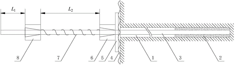
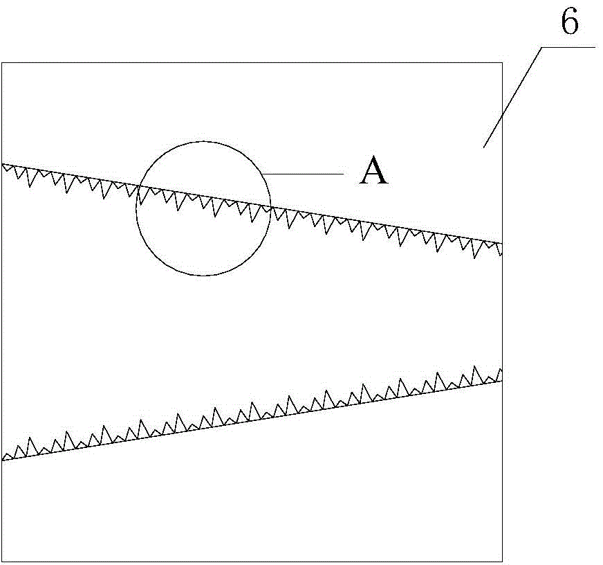
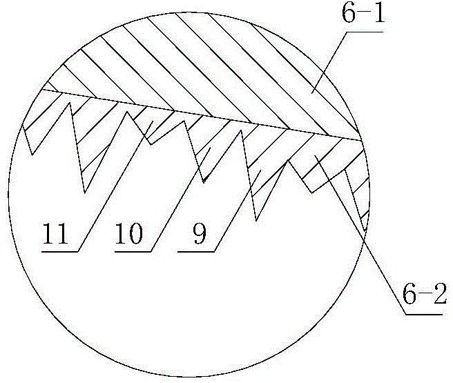
[0017] Such as figure 1 As shown, the simple micro-resistance and large-deformation anchoring device of the present invention is mainly composed of a pressure anchor 6, a guide spring 7 and a rooting anchor 8. The pressure anchor 6, the guide spring 7 and the rooting anchor 8 are arranged in sequence On the exposed section of the anchor cable 3, let the length of the compression anchor 6 be 1.5 to 2 times the length of the root anchor 8. The length of the anchor cable outside the root anchor 8 is L 1 Is 6~10cm, the length of the anchor cable between the anchor 6 and the root anchor 8 is L 2 Is 20 to 30 cm; the pressure letting anchor 6 includes an inner cone sleeve 6-1 with an inner cone hole, a clip 6-2 wedged with the inner cone sleeve 6-1, and the clip 6 2 There are 2 to 4 tooth-shaped letting threads with different diameters. The pitch of each tooth-li...


PUM


Abstract

The invention discloses a simple micro-added resistance large-deformation anchorage device and a simple micro-added resistance large-deformation anchorage method. The device mainly comprises a yielding anchorage device, a guide spring and a rooting anchorage device. Yielding is realized by the gradual damage of multiple threads in a clamping piece of the yielding anchorage device and the compressive deformation of the spring, so that large deformation of surrounding rocks is adapted, and micro-added resistance anchorage force is provided for the surrounding rocks; in such a process, the surrounding rocks can be yielded by 15 to 25cm, larger deformation of the surrounding rocks of a roadway can be adapted, and moreover, the micro-added resistance anchorage force can further be provided to slowly change the deformation of the roadway within a certain range in a deformation process of the roadway, so that the roadway can be well supported, the requirement of large deformation of the roadway can be met, and anchorage effect loss or failure of an anchor rope due to the excessive deformation of the roadway can be avoided. The device and the method can be better adapted to deep well and soft rock dynamic-pressure roadways, roadway maintenance cost is reduced, and the safety and the reliability of the roadway are improved.

Description

Technical field [0001] The invention relates to a simple micro-resistance-increasing and large-deformation anchoring device and method, which is especially suitable for supporting soft rock, dynamic pressure roadway and deep well roadway. Background technique [0002] Roadway deformation is an inevitable phenomenon in coal mine production and operation activities. The roadway deformation is mainly caused by the redistribution of stress in the surrounding rock after the roadway is excavated and the impact of mining activities. At present, bolt (cable) support is a widely used roadway support form for roadway deformation, which can be divided into bolt support and anchor cable support. The main function of anchor rod (cable) support is to restore the surrounding rock from a two-way stress state to a three-way stress state by applying anchoring force to the surrounding rock, thereby increasing the strength of the surrounding rock and giving full play to the self-carrying capacity of...

Claims


Application Information

Patent Timeline
Patent Type & Authority Applications(China)
IPC IPC(8): E21D21/00E21D20/02
CPCE21D20/02E21D21/0026
Inventor 郑西贵张强付世雄岳炜师超民张名
Owner CHINA UNIV OF MINING & TECH
Why Eureka
Try Eureka