Vortex flame combustion device with safety manual ignition

A flame combustion, vortex technology, applied in the direction of burner, combustion method, combustion type, etc., can solve the problem that the combustion device cannot reduce the flame height and the obvious vortex shape.

Active Publication Date: 2017-01-18
PRO IRODA INDS
View PDF9 Cites 0 Cited by
  • Summary
  • Abstract
  • Description
  • Claims
  • Application Information

AI Technical Summary

Problems solved by technology

[0007] The technical problem to be solved by the present invention is that the traditional combustion device for generating vortex flames cannot shrink and maintain a stable flame height and obvious vortex shape, and it can only be used when the flame scale is large and the length of the shield is long enough. In order to provide an obvious rotating flame effect, and when manually igniting, if it is used improperly, it is easy to make the gas accumulate at the bottom of the light transmission cover, resulting in flashing and endangering the safety of users.

Method used


Image

  • Vortex flame combustion device with safety manual ignition
  • Vortex flame combustion device with safety manual ignition
  • Vortex flame combustion device with safety manual ignition

Examples


Embodiment Construction

[0032] Regarding the technology, means and effects used in the present invention, a preferred embodiment is given and described in detail below with drawings, which are for illustration purposes only, and are not limited by this structure in the patent application.

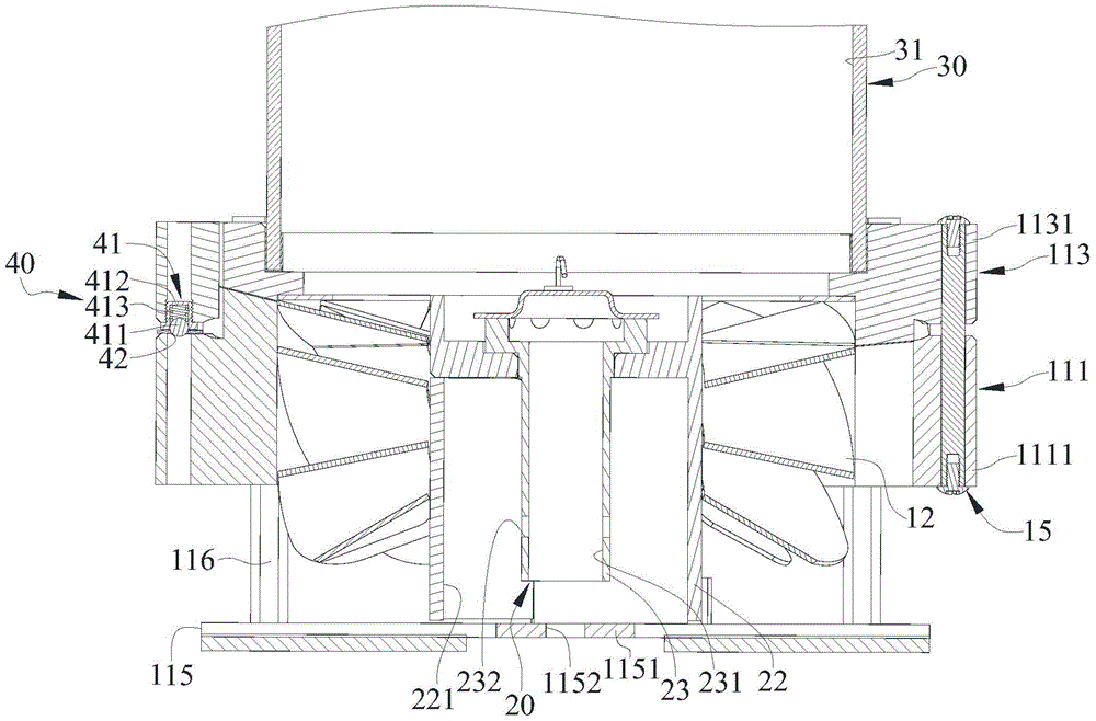
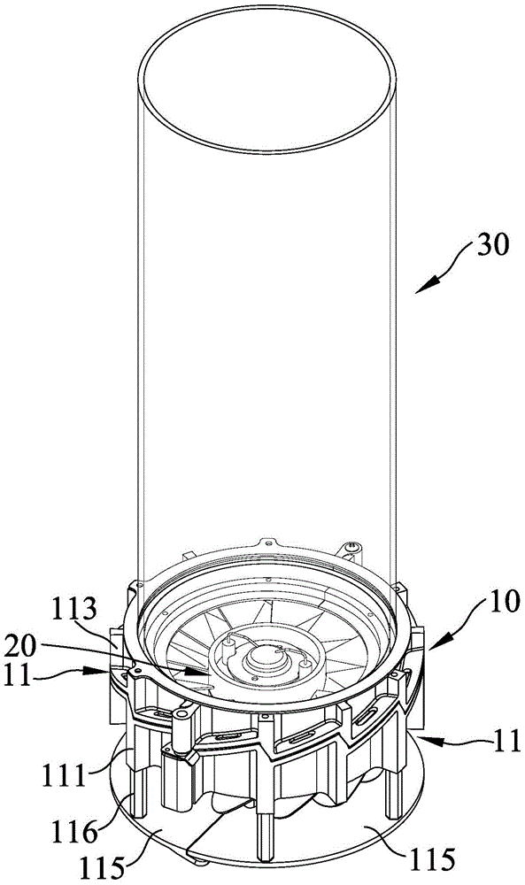
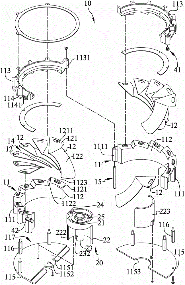
[0033] Please refer to Figure 1 to Figure 4 , is the three-dimensional appearance view, partial exploded view, top view and sectional view of the vortex flame combustion device with safety manual ignition of the present invention. The vortex flame combustion device with safety manual ignition of the present invention includes a diversion group 10 , a nozzle 20 and a cover body 30 .

[0034] The guide group 10 is slightly cylindrical in appearance and can be connected to a fuel tank (such as a gas tank). The guide group 10 includes two frames 11 and several blades 12. The structures of the two frames 11 are roughly symmetrical and Pivoted to each other, each of the blades 12 is helically distributed on the two fr...


PUM


Abstract

The invention relates to a scroll type flame combustion device with safety manual ignition. The device comprises a deflector group, a nozzle and a cover body. The deflector group can be connected with a fuel tank and contains two frame bodies and several blades. The two frame bodies are pivoted to each other. Each of the blades is spirally distributed on the two frame bodies. An air guide channel for letting the air pass through is formed between each two adjacent blades. The nozzle is arranged inside the deflector group and contains at least a vent hole which lets fuel inside the fuel tank pass through. One end of the deflector group, far away from the nozzle, is connected with the cover body. The cover body is prepared from a nonopaque material. The cover body encloses to form a limit space which is communicated with the vent hole of the nozzle.

Description

technical field [0001] The invention mainly discloses a flame combustion device with safe manual ignition, especially a combustion device capable of effectively generating swirling flames. Background technique [0002] Please refer to the US Patent No. 7097448 "VORTEX TYPE GAS LAMP" patent case, which discloses a vortex type gas lamp (gas lamp) for combustible gas to generate an upward vortex flame, and the vortex flame is located at a Surrounded and limited within the boundary of the vortex air, there will be an interface between the gas-free vortex air and the central area surrounded by the gas during operation, and the gas will burn inside it. The gas lamp has a central axis (axis) and includes: a base (base) with a surface extending laterally along the central axis; a shield (shield) including a first, a second axially extending block (section) , each block has an upper end and a lower end, the lower end of each block is fluid-tightly combined with the base, each block ...

Claims


Application Information

Patent Timeline
Patent Type & Authority Patents(China)
IPC IPC(8): F23C7/00F23D14/24
Inventor 陈维隆
Owner PRO IRODA INDS
Why Eureka
Try Eureka