Internal threaded heat-transfer copper pipe

A technology of internal thread and copper tube, applied in the field of internal thread heat transfer copper tube, can solve the problems of increased flow resistance of refrigerant and low heat exchange rate of refrigerant, and achieve the effect of reducing flow resistance of refrigerant and increasing heat exchange rate

Active Publication Date: 2015-05-27
JIANGXI NAILE COPPER IND
View PDF4 Cites 5 Cited by
  • Summary
  • Abstract
  • Description
  • Claims
  • Application Information

AI Technical Summary

Problems solved by technology

[0004] In order to solve the problems in the prior art that the thread on the inner wall of the copper tube causes the increase of the flow resistance of the refrigerant and the low heat exchange rate of the refrigerant in different parts of the heat transfer tube, the invention provides a method that can effectively reduce the flow resistance of the refrigerant and strengthen the copper tube body. Internal turbulence and turbulence effect, internally threaded heat transfer copper tube that improves the heat exchange rate inside and outside the copper tube body

Method used


Image

  • Internal threaded heat-transfer copper pipe
  • Internal threaded heat-transfer copper pipe
  • Internal threaded heat-transfer copper pipe

Examples


Embodiment 1

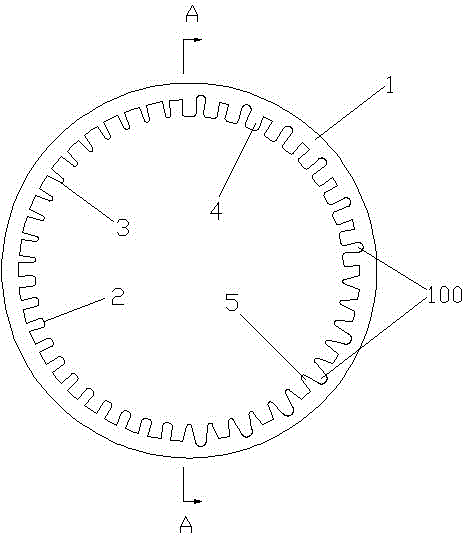
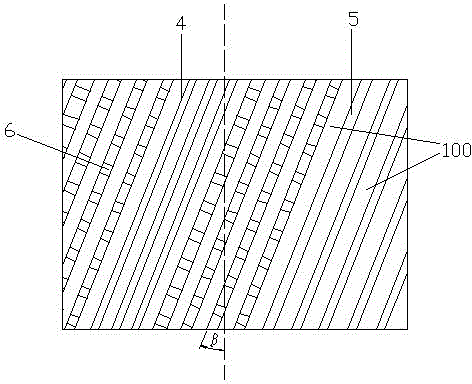
[0025] Embodiment 1: as figure 1 The shown internally threaded heat-transfer copper tube includes a copper tube body 1, and the inner wall of the copper tube body is provided with four sets of spirally distributed ribs along the circumferential direction, which are tooth ribs A2, tooth ribs B3, and tooth ribs a4 , tooth rib b5, on any section of the copper pipe body, the arc surfaces of tooth rib A, tooth rib B, tooth rib a, and tooth rib b each occupy a central angle of 90°, and the cross-sections of tooth rib A and tooth rib a are rectangular structure, the cross-sections of rib B and rib b are triangular, the ratio of the tooth width of rib A to the width of rib a is 1:1.2, the tooth tip angle of rib B is 8°, and the tooth width of rib b is The top angle is 25°, and the inner wall of the copper pipe body corresponding to tooth rib a and tooth rib b is also provided with heat dissipation grooves 100. The heat dissipation grooves are helically distributed along the direction ...

Embodiment 2

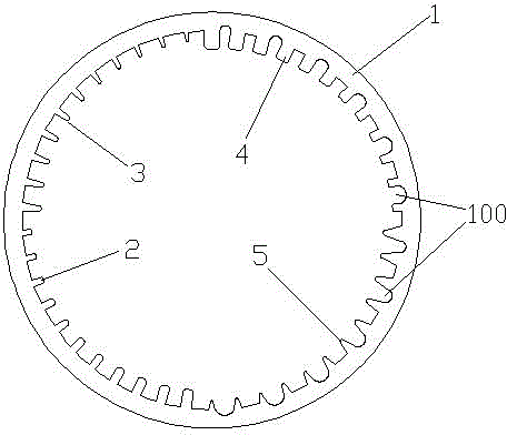
[0026] Embodiment 2: as figure 2The shown internal thread heat transfer copper tube includes a copper tube body 1, and the inner wall of the copper tube body is provided with four sets of spirally distributed tooth ribs along the circumferential direction, respectively tooth rib A2, tooth rib B3, and tooth rib a4 , tooth rib b5, on any section of the copper pipe body, the arc surfaces of tooth rib A, tooth rib B, tooth rib a, and tooth rib b each occupy a central angle of 90°, and the cross-sections of tooth rib A and tooth rib a are rectangular structure, the cross-sections of rib B and rib b are triangular, the ratio of the tooth width of rib A to the width of rib a is 1:1.6, the tooth tip angle of rib B is 20°, and the tooth width of rib b is The top angle is 40°, and the inner wall corresponding to the copper pipe body and tooth ribs a and tooth rib b is also provided with heat dissipation grooves 100. The heat dissipation grooves are helically distributed along the direc...

Embodiment 3

[0027] Embodiment 3: as Figure 4 The shown internal thread heat transfer copper tube includes a copper tube body 1, and the inner wall of the copper tube body is provided with four sets of spirally distributed tooth ribs along the circumferential direction, respectively tooth rib A2, tooth rib B3, and tooth rib a4 , tooth rib b5, on any section of the copper pipe body, the arc surfaces of tooth rib A, tooth rib B, tooth rib a, and tooth rib b each occupy a central angle of 90°, and the cross-sections of tooth rib A and tooth rib a are rectangular structure, the cross-sections of rib B and rib b are triangular, the ratio of the tooth width of rib A to the width of rib a is 1:1.4, the tooth tip angle of rib B is 14°, and the tooth width of rib b is The top angle is 32°, and the inner wall corresponding to the copper pipe body and tooth rib a and tooth rib b is also provided with heat dissipation grooves 100. The heat dissipation grooves are helically distributed along the direc...


PUM


Abstract

The invention relates to the technical field of heat-transfer pipes, and discloses an internal threaded heat-transfer copper pipe. The internal threaded heat-transfer copper pipe comprises a copper pipe body, wherein the inner wall of the copper pipe body is sequentially provided with four groups of toothed ribs in a spiral distribution along the circumferential direction; the four groups of toothed ribs include toothed ribs A, toothed ribs B, toothed ribs a and toothed ribs b; on any cross section of the copper pipe body, the arc surface of each group of the toothed ribs A, the toothed ribs B, the toothed ribs a and the toothed ribs b occupies a central angle of 90 degrees; the cross section of each of the toothed ribs A and the toothed ribs a is rectangular; the cross section of each of the toothed ribs B and the toothed ribs b is triangular; the tooth width ratio of one toothed rib A to one toothed rib a is 1:1.2 to 1:1.6; the addendum angle of each toothed rib B is 8-20 degrees; the addendum angle of each toothed rib b is 25-40 degrees; the inner wall, corresponding to the toothed ribs a and the toothed ribs b, of the copper pipe body is further provided with heat radiating grooves; at least two toothed ribs are distributed between two adjacent heat radiating grooves. Therefore, the internal threaded heat-transfer copper pipe has the beneficial effects that the refrigerant flow resistance can be effectively reduced, and the heat exchange rate of refrigerants at different parts in the copper pipe body is improved.

Description

technical field [0001] The invention relates to the technical field of heat transfer copper tubes, in particular to an internally threaded heat transfer copper tube. Background technique [0002] The condenser and evaporator in the air conditioner are made of internally threaded copper tube coils. In the field of heat transfer tube technology, the upgrade from light tubes to internally threaded copper tubes is a major technological innovation, which greatly improves the cooling performance of air conditioners. , heating performance, the current internally threaded copper pipes are generally a single spiral groove or helical teeth, and there are also many documents or patents that disclose helical teeth with different cross-sectional shapes, such as M-shaped, Y-shaped, trapezoidal, semicircular Tooth, various tooth shapes are nothing more than to increase the heat transfer surface area, but for internally threaded copper pipes, only changing the cross-sectional shape of the t...

Claims


Application Information

Patent Timeline
Patent Type & Authority Applications(China)
IPC IPC(8): F28F1/40F25B39/00
Inventor 刘晋龙罗奇梁梁子浩
Owner JIANGXI NAILE COPPER IND
Why Eureka
Try Eureka