Static correction method and equipment for converted wave

A technology of converted wave and static correction, applied in the field of geophysical exploration, can solve the problems of poor calculation accuracy and strict application conditions of converted waves near the surface, and achieve the effect of improving accuracy and effect

Active Publication Date: 2015-05-27
BC P INC CHINA NAT PETROLEUM CORP +1
View PDF2 Cites 14 Cited by
  • Summary
  • Abstract
  • Description
  • Claims
  • Application Information

AI Technical Summary

Problems solved by technology

[0006] In order to overcome the above-mentioned problems in the prior art, the present invention provides a method and equipment for static correction of converted waves, which solves the problems of strict applicable conditions and poor calculation accuracy in the prior art due to the complexity of converted waves near the surface , to a certain extent, it can adapt to the situation that the influence of the static correction on the detection point of the converted wave is greater than 1 / 2 period, and effectively improves the accuracy and efficiency of the static correction of the converted wave

Method used


Image

  • Static correction method and equipment for converted wave
  • Static correction method and equipment for converted wave
  • Static correction method and equipment for converted wave

Examples


Embodiment 1

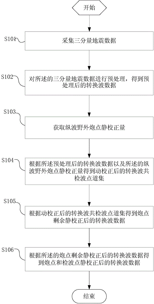
[0099] The invention provides a method for improving the accuracy and efficiency of converted wave static correction, which is applied to converted wave data static correction and optimizes conventional converted wave static correction. Figure 11 Schematic diagram of converted wave single-shot model recording after dynamic correction in Embodiment 1 provided for the present invention. There is no correction amount on the shot point, only the correction amount on the receiver point is left, so the remaining static correction amount of the shot point can not be calculated. Calculate the correction amount of the receiver point only on the shot point after dynamic correction. from Figure 11 It can be seen that the converted wave event jitters violently, indicating that the amount of correction of the receiver point is large, and the influence of the static correction exceeds half of the arrangement (the horizontal coordinate is the channel number, and the vertical coordinate is ...

Embodiment 2

[0101] Take the processing results of the present invention for actual seismic records as an example. Figure 13 is a dynamically corrected converted-wave single-shot actual seismic record, from Figure 13 It can be seen from the above that there are still some remaining corrections on the shot points, and if these corrections are not resolved, it will affect the accuracy of the invention to obtain the converted wave static corrections of the receiver point gathers. Therefore, before calculating the static correction of the receiver point, it is necessary to obtain and apply the residual static correction of the shot point. Figure 14 It is the result of the present invention calculating and applying the residual static correction amount of the shot point on the wave detection point. Figure 13 There is obvious event jitter in the above, the time window selected by the present invention is 1700 milliseconds to 2200 milliseconds, and this time window includes the event of abou...


PUM


Abstract

The invention provides a static correction method and static correction equipment for a converted wave. The method comprises the following steps: acquiring three-component earthquake data; performing preprocessing on the three-component earthquake data and obtaining preprocessed converted wave data; obtaining field shot static collection quantity of a longitudinal wave; according to the preprocessed converted wave data and the field shot static collection quantity of the longitudinal wave, obtaining common receiver gather of the converted wave subjected to dynamic correction; according to the common receiver gather of the converted wave subjected to dynamic correction, obtaining converted wave data after residual shot static correction; according to the converted wave data after residual shot static correction, obtaining converted wave data after static correction of shot points and receiver points. Problems of strict application conditions and poor calculation precision due to relatively complicated near surface of a converted wave in the prior art are solved, a situation that the time for static correction influence on the converted wave receiver points is greater than 1 / 2 of cycle is adapted to a certain extent, and the static correction precision and efficiency of the converted wave are effectively improved.

Description

technical field [0001] The present invention relates to the technical field of geophysical prospecting, in particular to multi-wave seismic prospecting technology, specifically a method and equipment for static correction of converted waves. Background technique [0002] Multi-wave seismic exploration is an exploration technology that comprehensively utilizes multiple information such as compressional waves, shear waves, and converted waves to carry out fine exploration of oil and gas reservoirs. This technology can identify thin interbeds, small faults, and low-amplitude structures, accurately predict reservoir boundaries and reservoir properties, monitor fluids, and even be directly used for oil and gas prediction. [0003] At present, with the continuous improvement and maturity of seismic exploration technology, converted wave exploration is increasing. The signal-to-noise ratio of converted wave seismic data is generally lower than that of P-wave. In addition, the stat...

Claims


Application Information

Patent Timeline
IPC IPC(8): G01V1/36
Inventor 熊定钰孙鹏远钱忠平程春华
Owner BC P INC CHINA NAT PETROLEUM CORP
Why Eureka
Try Eureka