
A test method for environmental adaptability of optical fiber sensing system

An optical fiber sensing system and environmental adaptability technology, applied in the direction of control/regulation system, non-electric variable control, instrument, etc., can solve the difficulty of finding component failures and design defects, reduce the severity of the test, and cannot find the root of the problem, etc. problems, to achieve the effect of easy failure and design defects, avoid repeated tests, and shorten test time

Active Publication Date: 2017-06-16
BANDWEAVER TECH CO LTD
View PDF2 Cites 0 Cited by
  • Summary
  • Abstract
  • Description
  • Claims
  • Application Information

AI Technical Summary

Problems solved by technology

In the current general method, either different samples are used to carry out environmental tests under different conditions, or the environmental tests under different conditions are incoherently carried out with the same sample, which is a non-combined test, which reduces the severity of the test and makes it difficult to find component failures. and design defects; or set environmental test conditions according to the requirements of specific standards or technical specifications, instead of simulating the extreme conditions during the use of the product, it is difficult to understand and grasp the use conditions and problems within the entire range of environmental conditions of the product's nominal ; or the product is not powered on or monitored online, and the status and problems of the product during the entire environmental test process cannot be monitored throughout the process, and the limit value of the product under these conditions cannot be understood, and the problems that may be found cannot be predicted. Or mastered enough to not be able to find the source of the problem

Method used


Image

  • A test method for environmental adaptability of optical fiber sensing system
  • A test method for environmental adaptability of optical fiber sensing system

Examples


Embodiment Construction

[0024] Below we will further describe in detail the method principle and operation process of the optical fiber sensing system environmental adaptability test of the present invention in conjunction with the accompanying drawings and specific embodiments, in order to understand its implementation process and working steps more deeply, but cannot In this way, the protection scope of the present invention is limited.

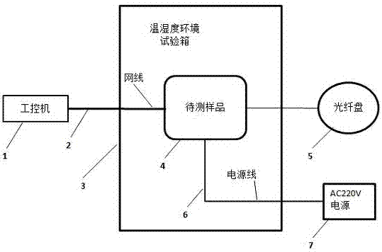
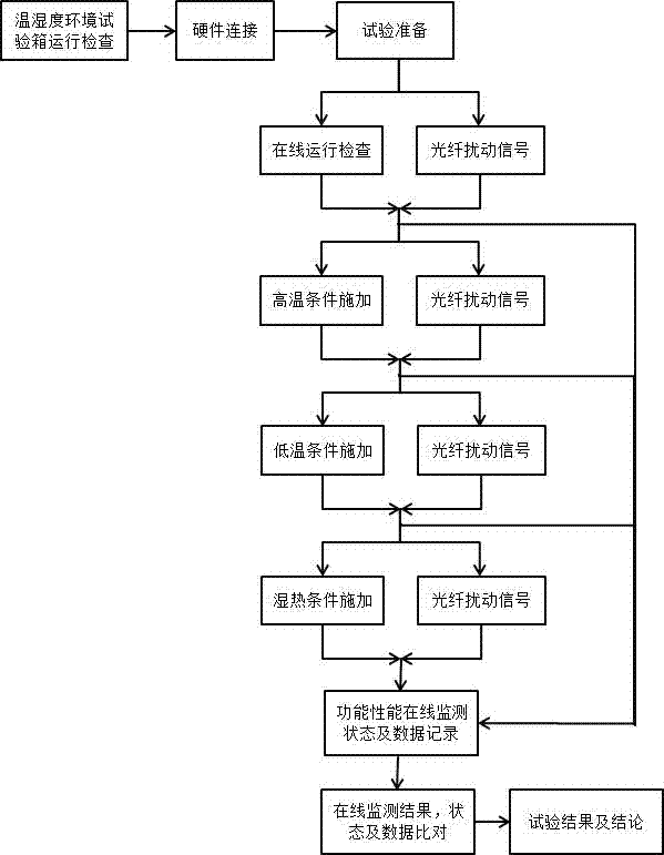
[0025] The purpose of the present invention is to provide a combined environmental adaptability test scheme, which simulates the temperature and humidity environment that may occur in the normal use of the product, and checks its operation in this environment; through the system control software in the external industrial computer and Optical fiber, real-time monitoring of product functional stability and performance changes in a simulated environment; and accelerated aging of product components to accelerate the exposure of product component failures and design de...


PUM


Abstract

The invention relates to a test method for the environmental adaptability of an optical fiber sensing system. The test method includes three parts: a hardware connection stage, a test preparation stage and a test stage: the hardware connection stage includes: preparing a temperature and humidity environment test box, and a prototype to be tested , industrial computer, double-layer shielded network cable, power cord and optical fiber disk; the test preparation stage includes: starting the prototype to be tested and the industrial computer and making the network communication between the two normal, and then opening the system control software in the industrial computer to start monitoring the operation of the prototype to be tested status; the test phase includes setting various temperatures and operations and monitoring test results to draw monitoring conclusions. The test method of the present invention selects the most severe working and operating temperature and humidity environment of the product, and allows the product to operate in its extreme environment, thereby providing assistance for device selection and design improvement. During the test, the product is run online and monitored in real time , by comparing the conditions and data before the test, under the high temperature test, under the low temperature test and under the damp heat test.

Description

technical field [0001] The invention relates to product reliability engineering technology, which is based on international and domestic industry standards, and is used for a reliability detection scheme for product development and design conforming to technical specifications. Background technique [0002] Reliability engineering started in the early 1950s from the research on the reliability of electronic equipment in the United States. In 1957, the U.S. Department of Defense established the Ad Hoc Committee on Missile Reliability, and the Institute of Electrical and Electronics Engineers (I.E.E.E.) regularly published Reliability Transactions. It was not until the 1960s that the reliability technology of electronic equipment was gradually extended to various industries such as machinery and construction. In 1965, the International Electronic Technology Committee (IEC) established the Reliability Technical Committee to coordinate reliability terms and definitions, reliabi...

Claims


Application Information

Patent Timeline
Patent Type & Authority Patents(China)
IPC IPC(8): G05D27/02
Inventor 张林周航宇谢丰权赵浩肖恺刘广贺
Owner BANDWEAVER TECH CO LTD
Learn More