Electronic igniter of gas equipment

An electronic igniter and equipment technology, applied in the direction of combustion ignition, ignition by electric spark, lighting and heating equipment, etc., can solve the problems that the ignition energy of the electronic igniter is easily affected by the outside world, and the production cost is high, so as to achieve low production cost, High ignition energy, easy installation and use

Inactive Publication Date: 2015-05-27
SICHUAN DITEL ELECTRONICS
0 Cites 0 Cited by

AI-Extracted Technical Summary

Problems solved by technology

[0002] Electronic igniters, generally for spark igniters, the main principle is that the inverter circuit works after power-on, and generates a high-frequency high voltage that is applied to the discharge electrode, spark discharge occurs to generate electric sparks, and...

Abstract

The invention discloses an electronic igniter of gas equipment. The electronic igniter comprises a first switch, a second switch, a third switch, a first resistor, a second resistor, a third resistor, a fourth resistor, a fifth resistor, a sixth resistor, a seventh resistor, an eighth resistor, a first diode, a second diode, a third diode, a fourth diode, a fifth diode, a sixth diode, a discharge tube, a first capacitor, a second capacitor, a third capacitor, a fourth capacitor, a fifth capacitor, a first NAND gate, a second NAND gate, a third NAND gate, a fourth NAND gate, a relay and a thyristor. The electronic igniter is simple in structure and circuit and convenient to mount and use, has the characteristics of high ignition energy, low manufacturing cost and the like, can be used for starting ignition during fuel oil combustion or gas combustion in the industrial field, and is a product worthy of popularization.

Application Domain

Electric spark ignitersAc-dc conversion

Technology Topic

CapacitanceEngineering +7

Image

  • Electronic igniter of gas equipment

Examples

  • Experimental program(1)

Example Embodiment

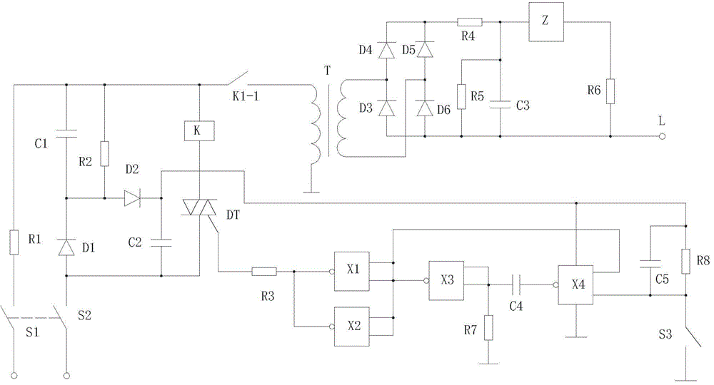
[0009] The present invention will be further explained below in conjunction with the drawings:
[0010] Such as figure 1 As shown, the present invention includes a first switch S1, a second switch S2, a third switch S3, a first resistor R1, a second resistor R2, a third resistor R3, a fourth resistor R4, a fifth resistor R5, and a sixth resistor R6. , Seventh resistor R7, eighth resistor R8, first diode D1, second diode D2, third diode D3, fourth diode D4, fifth diode D5, sixth diode Tube D6, discharge tube Z, first capacitor C1, second capacitor C2, third capacitor C3, fourth capacitor C4, fifth capacitor C5, first NAND gate X1, second NAND gate X2, third NAND Gate X3, fourth NAND gate X4, relay K and thyristor DT, the voltage input end of the power supply is connected to the first end of the first switch S1, and the second end of the first switch S1 is connected to the second end of the first resistor R1 , The first end of the first resistor R1 is simultaneously connected to the first end of the first capacitor C1, the first end of the second resistor R2, the first end of the relay K and the first end of the relay switch K1-1 of the relay K , The second end of the first capacitor C1 is simultaneously connected to the cathode of the first diode D1, the second end of the second resistor R2 and the anode of the second diode D2, and the anode of the first diode D1 is simultaneously connected to the The first end of the second switch S2, the second end of the second capacitor C2 and the second end of the thyristor DT are connected, the second end of the second switch S2 is connected to the voltage output end of the power supply, and the cathode of the second diode D2 is simultaneously Connected to the first terminal of the second capacitor C2, the voltage input terminal of the fourth NAND gate X4, the first terminal of the fifth capacitor C5 and the first terminal of the eighth resistor R8, the relay switch K1-1 of the relay K The second end is connected to the first end of the first winding of the transformer T, the second end of the first winding of the transformer T is grounded, and the second end of the second winding of the transformer T is simultaneously connected to the third diode D3 The cathode is connected to the anode of the fourth diode D4, and the second end of the second winding of the transformer T is simultaneously connected to the cathode of the sixth diode D6 and the anode of the fifth diode D5. The fourth diode D4 The cathode of is connected to the cathode of the fifth diode D5 and the first end of the fourth resistor R4 at the same time, and the second end of the fourth resistor R4 is simultaneously connected to the first end of the fifth resistor R5 and the first end of the third capacitor C3. Connected to the first end of the discharge tube Z, the second end of the discharge tube Z is connected to the first end of the sixth resistor R6, and the second end of the sixth resistor R6 is simultaneously connected to the second end and the fifth resistor of the third capacitor C3 The second terminal of R5, the anode of the sixth diode D6, and the anode of the third diode D3 are connected to the signal output terminal L, the control terminal of the thyristor DT is connected to the first terminal of the third resistor R3, and the third resistor R3 The second end of the first NAND gate X1 and the first end of the second NAND gate X2 are connected at the same time, and the first output end of the first NAND gate X1 is simultaneously connected to the first end of the first NAND gate X1. Two output terminals, the first output terminal of the second NAND gate X2 and the second output terminal of the second NAND gate X2, the first terminal of the third NAND gate X3 and the second output terminal of the fourth NAND gate X4 Connected, the first output terminal of the third NAND gate X3 is simultaneously connected to the first terminal of the fourth capacitor C4, the first terminal of the seventh resistor R7 and the third NAND gate X3 The second output terminal is connected, the second terminal of the seventh resistor R7 is grounded, the second terminal of the fourth capacitor C4 is connected to the first terminal of the fourth NAND gate X4, and the ground terminal of the fourth NAND gate X4 is grounded. The second output terminal of the NAND gate X4 is simultaneously connected to the second terminal of the fifth capacitor C5, the first terminal of the third switch S3 and the second terminal of the eighth resistor R8, and the second terminal of the third switch S3 is grounded.

PUM

no PUM

Description & Claims & Application Information

We can also present the details of the Description, Claims and Application information to help users get a comprehensive understanding of the technical details of the patent, such as background art, summary of invention, brief description of drawings, description of embodiments, and other original content. On the other hand, users can also determine the specific scope of protection of the technology through the list of claims; as well as understand the changes in the life cycle of the technology with the presentation of the patent timeline. Login to view more.

Similar technology patents

Elevator safety monitoring and pre-warning system

Owner:XIAN ZHONGZHI HUIZE PHOTOELECTRIC TECH

Electrical control system of double housing planer

InactiveCN105643359ASimple structure and circuitEasy maintenance and repair
Owner:THE NORTHWEST MACHINE

Start-up and excitation system of gas turbine generator set, method

ActiveCN109274300ASave installation spaceSimple structure and circuit
Owner:AVIC PST NANFANG GAS TURBINE COMPLETE MFG & INSTALLATION

Packaging carton with inflatable buffer air cushion

InactiveCN108502367Aoverall simplicityEasy to install and use
Owner:苏州震嵘包装有限公司

Classification and recommendation of technical efficacy words

  • Easy to install and use
  • Simple structure and circuit

Start-up and excitation system of gas turbine generator set, method

ActiveCN109274300ASave installation spaceSimple structure and circuit
Owner:AVIC PST NANFANG GAS TURBINE COMPLETE MFG & INSTALLATION

Electrical control system of double housing planer

InactiveCN105643359ASimple structure and circuitEasy maintenance and repair
Owner:THE NORTHWEST MACHINE
Why Eureka
Try Eureka