Detection method for position of rotor in full-speed domain of permanent magnet synchronous motor without position sensor

A permanent magnet synchronous motor, rotor position detection technology, applied in electronic commutation motor control, electrical components, electronic commutator and other directions, can solve the problem that the back electromotive force method is not suitable for use at low speed, affecting the accuracy of position estimation, motor stability, Back EMF is not easy to detect and other problems, to achieve the effect of reliable, easy-to-implement and smooth switching

Inactive Publication Date: 2015-05-27
SHENYANG INST OF AUTOMATION - CHINESE ACAD OF SCI
View PDF4 Cites 9 Cited by
  • Summary
  • Abstract
  • Description
  • Claims
  • Application Information

AI Technical Summary

Problems solved by technology

Since the amplitude of the back EMF is proportional to the speed, it is difficult to detect the back EMF at low speeds, so the back EMF method is not suitable for use at low speeds
When the motor is running at high speed, the high-frequency signal injection method will cause system vibration and torque ripple, which will affect the accuracy of position estimation and the stability of the motor operation, so the high-frequency signal injection method is not suitable for high-speed use

Method used


Image

  • Detection method for position of rotor in full-speed domain of permanent magnet synchronous motor without position sensor
  • Detection method for position of rotor in full-speed domain of permanent magnet synchronous motor without position sensor
  • Detection method for position of rotor in full-speed domain of permanent magnet synchronous motor without position sensor

Examples


Embodiment Construction

[0024] The present invention will be further described in detail below in conjunction with the accompanying drawings and embodiments.

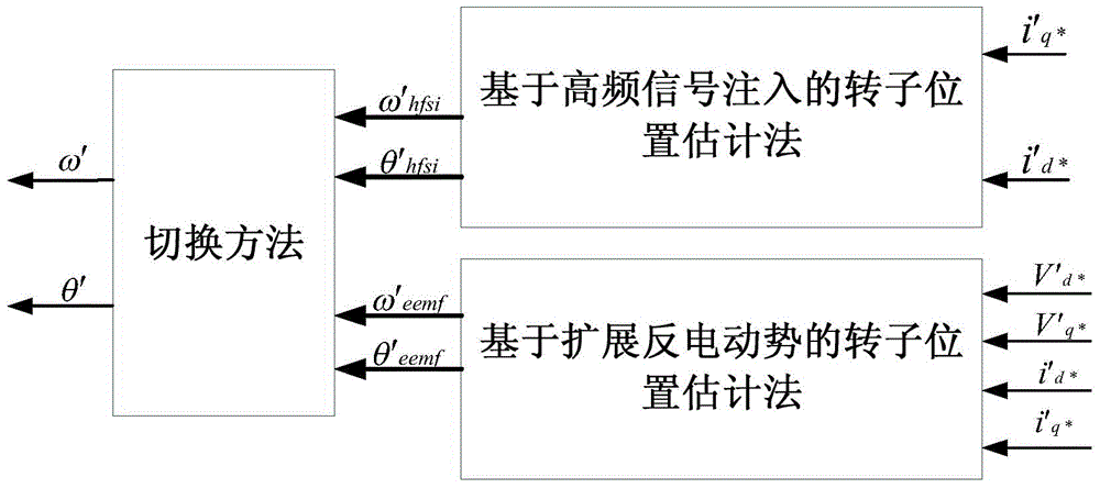
[0025] The method of the invention mainly includes: a rotor position estimation method based on high-frequency signal injection, a rotor position estimation method based on extended counter electromotive force and a switching method. The present invention uses the high-frequency signal injection method to estimate the position of the rotor at low speed, and designs a switching method. When the back electromotive force is large enough, it switches to the extended back electromotive force method to estimate the position of the rotor. The present invention effectively integrates the The above two methods make it a position sensorless permanent magnet synchronous motor rotor position detection method that can be used in the full speed range.

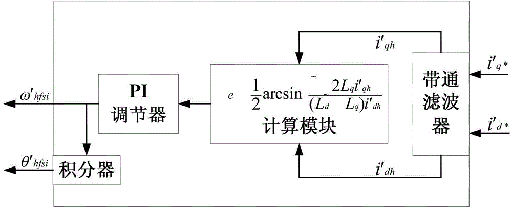
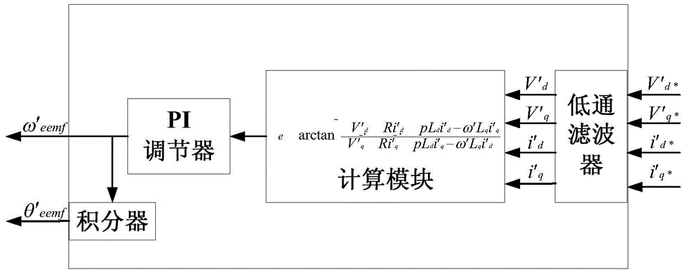
[0026] On the one hand, the present invention provides a rotor position estimation method based on high-f...


PUM


Abstract

The invention discloses a detection method for position of a rotor in a full-speed domain of a permanent magnet synchronous motor without a position sensor. The detection method mainly comprises a high-frequency signal injection method, an extended back electromotive force method and a switching method. When the motor is stationary or operates at a low speed, the high-frequency signal injection method is used for estimating the position of the rotor, and the switching method is designed, so that when back electromotive force is large enough, the high-frequency signal injection method is switched to the extended back electromotive force method to estimate the position of the rotor. According to the detection method disclosed by the invention, the two methods are effectively integrated through the designed switching method, so that the detection method for the position of the rotor of the permanent magnet synchronous motor without the position sensor can be used in a full-speed range and is high in detection precision and easy to implement.

Description

technical field [0001] The invention relates to a position sensorless control technology of a permanent magnet synchronous motor, in particular to a position sensorless permanent magnet synchronous motor rotor position detection method in the full speed range. Background technique [0002] In order to control the position of the permanent magnet synchronous motor, it is necessary to continuously detect the position of the motor rotor during its operation. Generally speaking, mechanical sensors are used to detect the position of the rotor, but the use of mechanical sensors affects the performance of permanent magnet synchronous motors, so the rotor position detection technology without using sensors has become a research field of permanent magnet synchronous motor control. key problem. The existing methods are mainly divided into three types: rotor position detection technology based on permanent magnet synchronous motor model calculation, rotor position detection technology...

Claims


Application Information

Patent Timeline
Patent Type & Authority Applications(China)
IPC IPC(8): H02P6/18H02P6/16
CPCH02P6/182
Inventor 刘明佟新鑫朱丹
Owner SHENYANG INST OF AUTOMATION - CHINESE ACAD OF SCI
Why Eureka
Try Eureka