Transport lock, in particular for the piston of a clutch release bearing

A locking device and release bearing technology, applied in clutches, friction clutches, fluid-driven clutches, etc., can solve problems such as release bearing slippage

Active Publication Date: 2015-05-27
SCHAEFFLER TECH AG & CO KG
View PDF6 Cites 4 Cited by
  • Summary
  • Abstract
  • Description
  • Claims
  • Application Information

AI Technical Summary

Problems solved by technology

However, due to rocking on the transport path, the cap-shaped locking element is released from the hous

Method used


Image

  • Transport lock, in particular for the piston of a clutch release bearing
  • Transport lock, in particular for the piston of a clutch release bearing
  • Transport lock, in particular for the piston of a clutch release bearing

Examples


Embodiment Construction

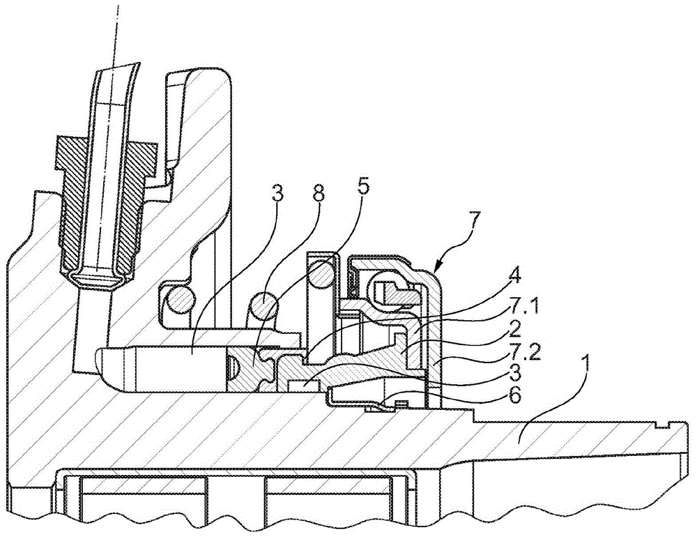
[0022] exist figure 1 shows a partial longitudinal section of a slave cylinder having a housing 1 with a circumferential housing surface 1.1 on which a piston 2 is arranged concentrically and axially movable . A seal 5 , which seals between the housing 1 and the piston 2 in the annular groove 3 of the housing 1 , is seated on one end of the piston 2 by means of the seal receptacle 4 . A release bearing 7 is connected to the other end of the piston 2 . The piston 2 is pressed onto the retaining ring 6 by means of a spring 8 which is supported on a not drawn radially outwardly directed flange of the housing 1 and via the release bearing 7 (via its inner ring 7.1) On the piston 2, said retaining ring is fixed axially firmly on the housing. The inner ring 7 . 1 of the release bearing 7 is fixed on the end of the piston 2 facing away from the seal 5 .

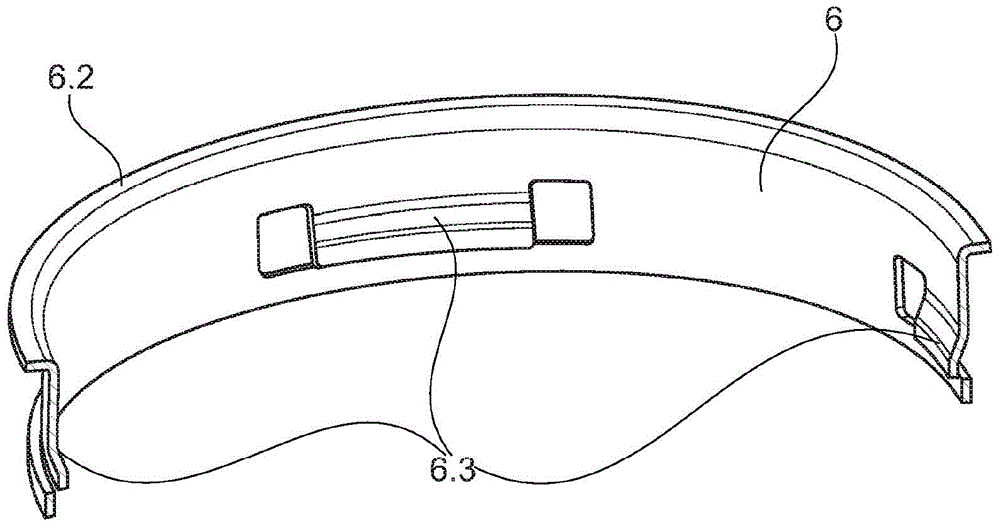
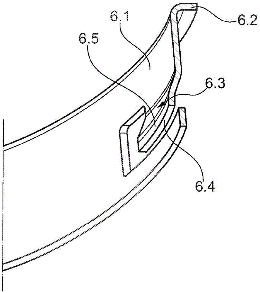
[0023] figure 2 It is shown that the retaining ring 6 has four detent hooks 6 . 3 which are arranged offset to one another a...


PUM


Abstract

The invention relates to a release device for the hydraulic clutch actuation of vehicles, said device comprising a slave cylinder arranged concentrically around a transmission input shaft, the annular piston of said cylinder being axially displaceable inside a housing, being connected to a clutch release bearing and being arranged radially outside said release bearing. At least one stop element is proviced in order to restrict the axial displacement of the annular piston. According to the invention, the clutch release bearing that is connected to the annular piston can be brought axially into contact with the stop element.

Description

technical field [0001] The invention relates to a transport lock, in particular for a piston of a release bearing, and is used, for example, in release systems for conventional clutches. Background technique [0002] From the publication DE 10 2009 035 913 A1 is known a transport locking device for an axially movable, concentrically arranged component of a clutch or a transmission of a motor vehicle, in particular for a concentrically arranged slave cylinder Transport lock for release bearing on housing. For this purpose, the locking element, which acts as a stop for the axially movable release bearing, can be pushed in the axial direction on the housing and can be clamped in the locked position under prestress. However, due to the jolting on the transport path, the cap-like locking element is released from the housing, whereby the risk of the release bearing slipping out of the housing of the output cylinder arises. [0003] According to a solution that has not yet been p...

Claims


Application Information

Patent Timeline
IPC IPC(8): F16D25/08
CPCF16D25/083F16D25/087F16D2013/581F16D2500/1066F16D25/12
Inventor 丹尼尔·博什尼亚克
Owner SCHAEFFLER TECH AG & CO KG
Why Eureka
Try Eureka