
Hair clipper cutter and manufacturing method thereof

A manufacturing method and technology for hair clippers, which are applied in metal processing and other directions, can solve the problems of reduced life of grinding wheels, reduced shearing efficiency, and laborious shearing, and achieve the effects of reducing hot problems, improving shearing efficiency, and reducing power consumption.

Inactive Publication Date: 2017-05-31
姚自强
View PDF6 Cites 0 Cited by
  • Summary
  • Abstract
  • Description
  • Claims
  • Application Information

AI Technical Summary

Problems solved by technology

[0005] 2. In addition, if Figure 3B As shown, because the bottom of the V-shaped alveolar 12 can be narrowed, so the hair 5 that enters the bottom of the V-shaped alveolar 12 as mentioned above can be squeezed, so the hair bundles can be tightly concentrated, and when cutting , the tightly concentrated hair strands will make the cutting more laborious, so there will be situations that reduce the cutting efficiency;
[0006] 3. Due to the large friction area at the bottom, the blade is more likely to heat up and become hot during use;
[0007] 4. Larger friction area results in higher power consumption;
[0008] 5. The above-mentioned processing method will increase the processing amount of the grinding wheel, reduce the life of the grinding wheel, and lead to the problem of increasing the processing cost.

Method used


Image

  • Hair clipper cutter and manufacturing method thereof
  • Hair clipper cutter and manufacturing method thereof
  • Hair clipper cutter and manufacturing method thereof

Examples


Embodiment Construction

[0041] Other technical contents, features and functions of the present invention will be clearly presented in the following detailed description of preferred embodiments with reference to the drawings.

[0042] see Figure 4 , 5 , 6, is the unprocessed blade structure schematic diagram of the cutting tool of the hair clipper of the present invention and its manufacturing method, the partially processed blade structure schematic diagram and the processed blade structure schematic diagram, and the movable blade is used as an example in the present invention , but the knife structure and manufacturing method disclosed in the present invention can also be used for fixed blades, and in this embodiment, a punching device (not shown) is used to punch out a movable blade with several circular penetration holes 411 4. It is characterized in that: the circular penetration hole 411 is located on the flat surface 41 at the front end of the movable blade 4, and the movable blade 4 formed ...


PUM


Abstract

A cutter of a hair clipper and a method of manufacturing the same are provided. A half processing blade having multiple circular penetrating holes is punched by punching equipment. Grinding wheel equipment is utilized to cut and machine the front end of each circular penetrating hole of the half processing blade toward the direction of the circular penetrating hole so that two corresponding blade portions are formed. In this way, multiple tooth units are manufactured on the movable blade. The cutter is characterized in that two side surfaces of the front end of any tooth unit are provided with the blade portions, and an arc groove hole is formed between the bottom end on any side of any tooth unit and the bottom end of one adjacent tooth unit.

Description

technical field [0001] The present invention relates to a cutting tool for a hair clipper and its manufacturing method, in particular to a process of processing a relatively thick metal plate into a cutting tool, and the structure of the cutting tool can improve the cutting efficiency and make the trimmed hair relatively flat. Background technique [0002] The blade of the hair clipper usually consists of a stationary fixed blade and a movable blade superimposed on the fixed blade, and the movable blade can move back and forth to cut the hair alternately with the fixed blade. [0003] In order to achieve a good cutting effect of the hair clipper blade and maintain a durable and stable performance, the current common technique is to choose a thicker metal plate material, and then use a grinding wheel to cut out the tooth profile, so that the tooth profile has an acute angle and maintains the same thickness. For structural strength, please refer to Figure 1A As shown in , it...

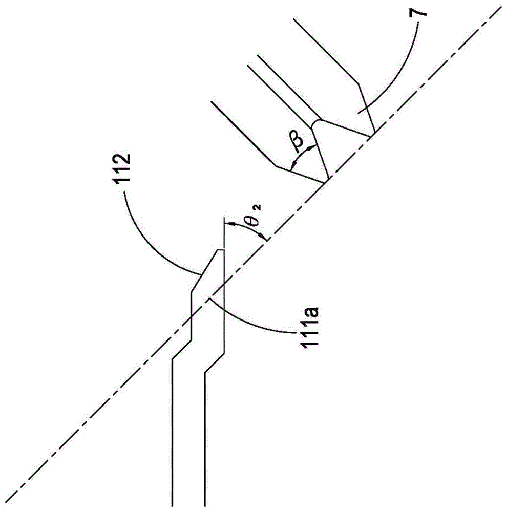
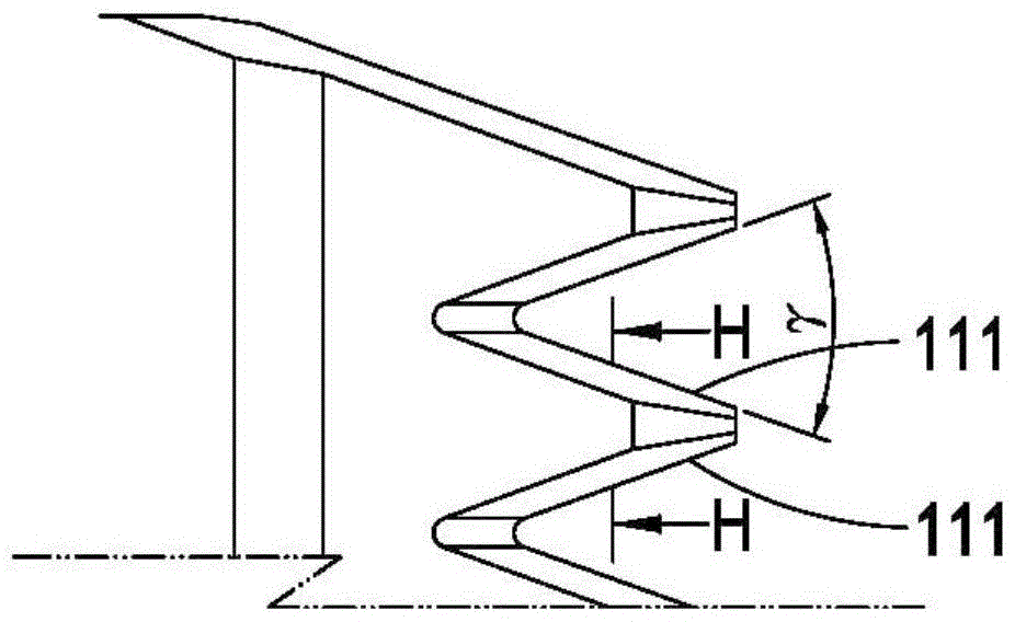
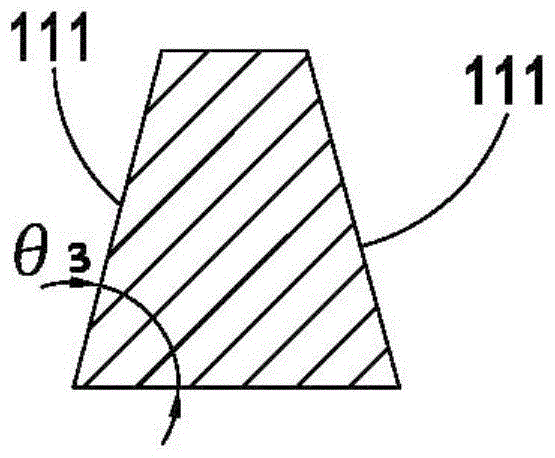
Claims


Application Information

Patent Timeline
Patent Type & Authority Patents(China)
IPC IPC(8): B26B19/04B26B19/06B23P15/28
Inventor 姚自强
Owner 姚自强
Learn More