Portal crane for roads and bridges

A technology for gantry cranes and road bridges, applied in the direction of the clockwork mechanism, load hanging elements, hoisting devices, etc., can solve the problem of affecting the service life of the wire rope, reducing the effective working stroke of the gantry crane, and increasing the risk of wire rope breakage, etc. question

Inactive Publication Date: 2022-04-15
CHONGQING VOCATIONAL COLLEGE OF TRANSPORTATION
View PDF0 Cites 0 Cited by
  • Summary
  • Abstract
  • Description
  • Claims
  • Application Information

AI Technical Summary

Problems solved by technology

[0002] With the development of the economy, more and more cranes are used in construction, which brings convenience to the construction. In particular, gantry cranes are widely used in road and bridge construction. Electric hoists are an important part of gantry cranes. Due to the length and size of electric hoists Large, resulting in the reduction of the effective working stroke of the gantry crane (the length of the electric hoist moving along the main beam of the gantry crane minus the length of the electric hoist is equal to the effective working stroke of the gantry crane), so the length of the electric hoist needs to be set relatively short, so that The steel wire rope is wound in multiple layers on the steel wire rope take-up roller. However, the mutual extrusion and friction between the steel wire ropes will make the steel wires of the steel wire rope loose and increase the risk of breaking the steel wire rope, thus affecting the service life of the steel wire rope. The speed adjustment structure is complicated and cannot meet the actual needs, so we invented an electric hoist for road and bridge gantry cranes

Method used


Image

  • Portal crane for roads and bridges

Examples


Embodiment Construction

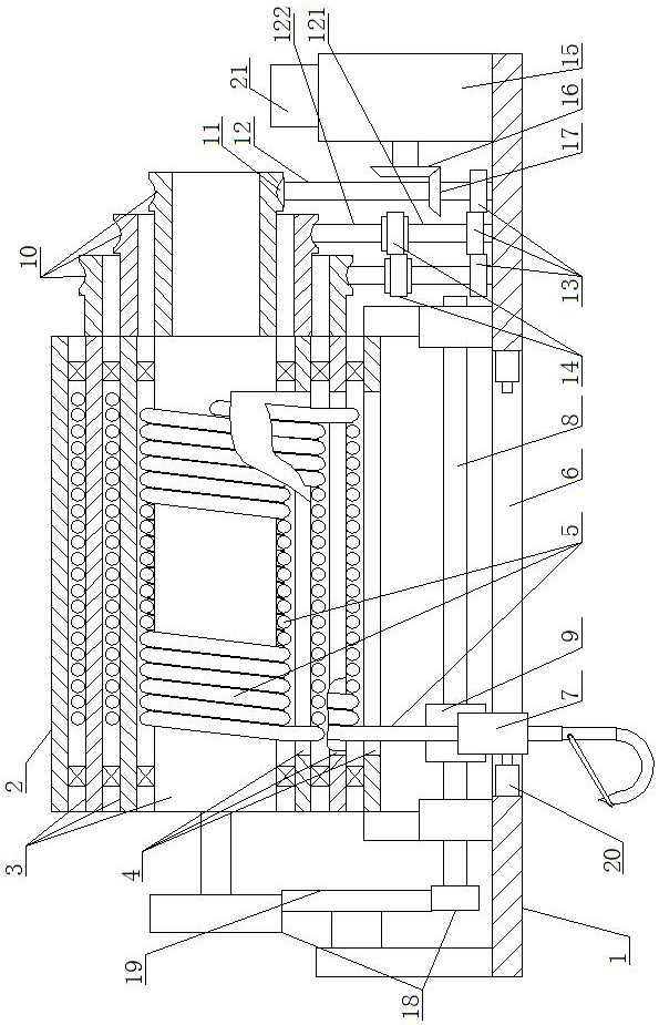
[0012] In order to make the purpose, technical solutions and advantages of the embodiments of the present invention clearer, the technical solutions in the embodiments of the present invention will be clearly and completely described below in conjunction with the drawings in the embodiments of the present invention. Obviously, the described embodiments It is a part of embodiments of the present invention, but not all embodiments. Based on the embodiments of the present invention, all other embodiments obtained by persons of ordinary skill in the art without creative efforts fall within the protection scope of the present invention.

[0013] A gantry crane for roads and bridges, as shown in the figure, includes a base 1, an outer cylinder 2 is fixedly installed on the base 1, and several coaxial inner cylinders 3 are installed in rotation inside the outer cylinder 2, and the inner diameter of the inner cylinder 3 is from the inside to the outside Gradually increase, the two end...


PUM


Abstract

A portal crane for roads and bridges comprises a base, an outer barrel is fixedly mounted on the base, a plurality of coaxial inner barrels are rotatably mounted in the outer barrel, the inner diameters of the inner barrels are gradually increased from inside to outside, strip-shaped through grooves are formed in the bottom sides of the inner barrels and the bottom side of the outer barrel respectively, and one side of the periphery of the inner barrel on the innermost side is fixedly connected with one end of a steel wire rope. A nut is installed on the periphery of the reciprocating lead screw in a threaded fit mode, the sleeve is fixedly connected with the nut, a driving device capable of driving the inner barrels to rotate is arranged on the base, and when one inner barrel rotates, the inner barrel inside the inner barrel synchronously rotates along with the inner barrel, and the inner barrel outside the inner barrel is static. The device is simple in structure and ingenious in conception, multiple layers of steel wire ropes are wound on different inner barrels, extrusion and abrasion between the steel wire ropes are reduced, the service life of the steel wire ropes is prolonged, the steel wire ropes are wound on the inner barrels with different diameters, the steel wire rope winding and unwinding speed is adjusted, the market requirement can be met, and the device is suitable for popularization.

Description

technical field [0001] The invention belongs to the field of gantry cranes, in particular to a gantry crane for roads and bridges. Background technique [0002] With the development of the economy, more and more cranes are used in construction, which brings convenience to the construction. In particular, gantry cranes are widely used in road and bridge construction. Electric hoists are an important part of gantry cranes. Due to the length and size of electric hoists Large, resulting in the reduction of the effective working stroke of the gantry crane (the length of the electric hoist moving along the main girder of the gantry crane minus the length of the electric hoist is equal to the effective working stroke of the gantry crane), so the length of the electric hoist needs to be set relatively short, so that The steel wire rope is wound in multiple layers on the steel wire rope take-up roller. However, the mutual extrusion and friction between the steel wire ropes will make ...

Claims


Application Information

Patent Timeline
IPC IPC(8): B66C13/22B66D1/12B66D1/14B66D1/28
Inventor 刘东霞唐莉
Owner CHONGQING VOCATIONAL COLLEGE OF TRANSPORTATION
Why Eureka
Try Eureka