Control valve for a vehicle brake system and vehicle brake system comprising such a control valve

A vehicle braking and regulating valve technology, applied in the field of regulating valves, can solve the problems of increased closing pressure hysteresis and high control pressure, and achieve the effect of preventing pre-pressure from rising

Active Publication Date: 2011-05-18
ROBERT BOSCH GMBH
View PDF5 Cites 11 Cited by
  • Summary
  • Abstract
  • Description
  • Claims
  • Application Information

AI Technical Summary

Problems solved by technology

The control pressure for actuating the control valves 40, 40' should therefore be relatively high, at the same time the friction of the sealing elements leads to an increase in the hysteresis of the closing pressure

Method used


Image

  • Control valve for a vehicle brake system and vehicle brake system comprising such a control valve
  • Control valve for a vehicle brake system and vehicle brake system comprising such a control valve
  • Control valve for a vehicle brake system and vehicle brake system comprising such a control valve

Examples


Embodiment Construction

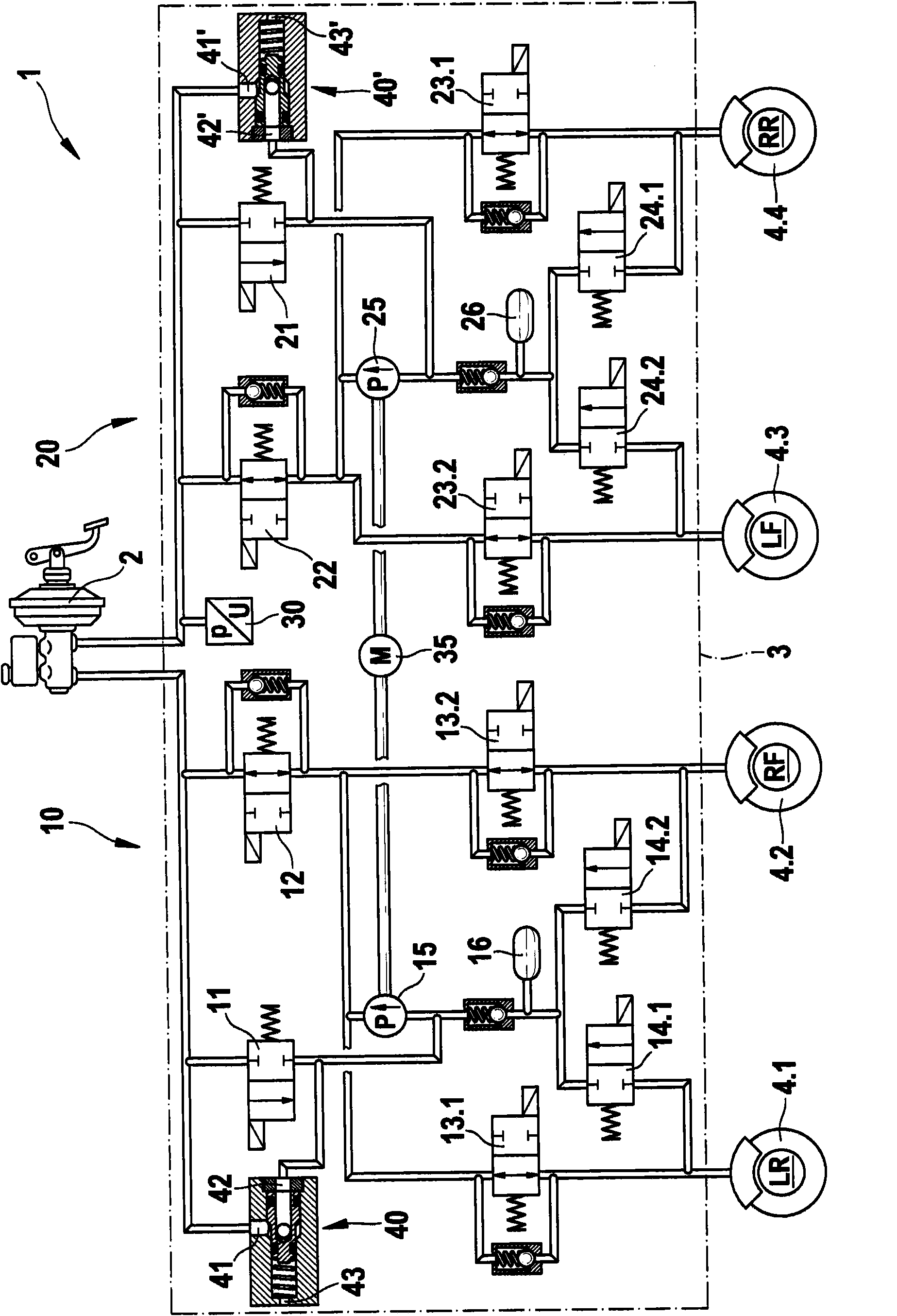
[0025] exist Figure 4 The embodiment shown in the vehicle braking system 1' according to the present invention is basically as according to figure 1 The conventional vehicle braking system 1 is configured like a conventional vehicle brake system 1 and comprises the same components except for the first regulating valve 50 and the second regulating valve 50 ′, which perform the same or similar functions. The exemplary embodiment of the vehicle brake system 1' according to the invention therefore comprises the master brake cylinder 2, the fluid control unit 3' shown in dotted lines and four wheel brakes 4.1 to 4.4, each with a corresponding not shown wheel brake cylinders. Two wheel brakes of the four wheel brakes 4 . Thus, a first wheel brake 4.1 and a second wheel brake 4.2 are assigned to the first brake circuit 10', wherein the first wheel brake 4.1 is arranged, for example, on the left side of the rear axle of the vehicle, and the second wheel brake 4.2 is arranged, for e...


PUM


Abstract

The invention relates to a control valve (50) for a vehicle brake system having a first fluid connection (51), a second fluid connection (52), and a decompressed connection (53) toward the atmosphere, wherein an adjustment spring (55) applies a spring force to a control piston (54) moving in longitudinal direction on the decompressed side, said control piston completely releasing a fluid connection between the first fluid connection (51) and the second fluid connection (52) in an initial position, and to a corresponding vehicle brake system comprising such a control valve (50). According to the invention the control valve (50) comprises a valve body (60) having a seal seat (61) and a sealing element (59) coupled to a control piston (54), wherein a sealing region (59.2) of the sealing element (59) interacts with the seal seat (61) of the valve body (60) in order to limit an effective pressure present on the second fluid connection (52) to a predetermined maximum pressure value, wherein an effective diameter (58.1) of the control piston (54) is greater than or equal to an effective diameter (58.2) of the sealing element (59).

Description

technical field [0001] The invention relates to a regulating valve for a vehicle braking system according to the preamble of independent claim 1 . Background technique [0002] Vehicle braking systems are known from the prior art, which include various safety systems (such as anti-lock braking systems (ABS), electronic stability program systems (ESP), etc.) and various Safety functions (such as anti-lock function, actuation anti-skid control (ASR), etc.). figure 1 A vehicle braking system is shown by which various safety functions can be performed [0003] as by figure 1 It can be seen that a conventional vehicle braking system 1 comprises a master brake cylinder 2, a fluid control unit 3 shown in dotted lines and four wheel brakes 4.1 to 4.4 each having a corresponding wheel not shown brake cylinder. Two wheel brakes of the four wheel brakes 4 . Thus, the first wheel brake 4.1 and the second wheel brake 4.2 are assigned to the first brake circuit 10, wherein the first ...

Claims


Application Information

Patent Timeline
Patent Type & Authority Applications(China)
IPC IPC(8): B60T8/34F16K17/30
CPCF16K31/1223F15B13/025B60T8/4872B60T8/341
Inventor R·舍普N·阿拉策
Owner ROBERT BOSCH GMBH
Why Eureka
Try Eureka