Partitioned paving molding die and method for multi-bundle and multi-positioning girder belts

A technology for forming molds and girder belts, which is applied in the field of composite material forming, can solve problems affecting the bearing effect of flexible beam girder belts, girder wrinkles, broken yarns and disordered yarns, and insufficient operating space, so as to achieve convenient implementation and avoid disordered yarns And the girder with wrinkles, the effect of ensuring quality

Inactive Publication Date: 2015-06-03
CHANGHE AIRCRAFT INDUSTRIES CORPORATION
View PDF3 Cites 1 Cited by
  • Summary
  • Abstract
  • Description
  • Claims
  • Application Information

AI Technical Summary

Problems solved by technology

The winding and laying of the girder belt is the key link in the forming process. In order to ensure the accurate positioning of the four bushings, the commonly used girder belt laying and forming tooling is an integral form, that is, the four positioning bushings are fixed on the same tooling template , so that each bundle of girder belts is wound and paved around the bushings at both ends. Because the distance between the two beams at the front and rear edges of the structure is narrow (about 3.5mm at the narrowest position), the operating space for the winding process is insufficient, and it is easy to be damaged during the winding process of the girders. Wrinkles, broken yarns and random yarns will affect the load-bearing effect of the final flexible beam girder belt

Method used


Image

  • Partitioned paving molding die and method for multi-bundle and multi-positioning girder belts
  • Partitioned paving molding die and method for multi-bundle and multi-positioning girder belts
  • Partitioned paving molding die and method for multi-bundle and multi-positioning girder belts

Examples


Embodiment

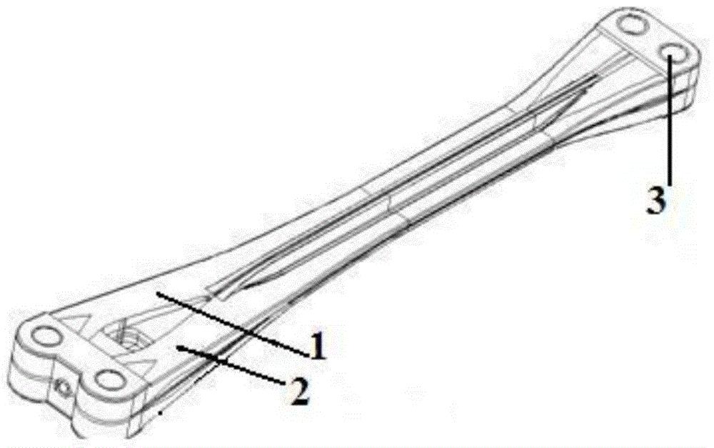
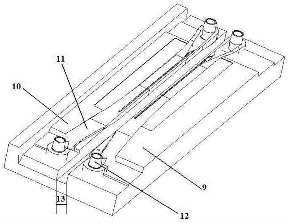
[0022] Example: such as figure 1 , a composite material flexible beam composed of multi-beam number and multi-position girder strips. Such as Figure 5 , the piece is divided into pieces and pasted into forming tools. The structural characteristics of the lower mold body are: the symmetrical position of the front and rear edges of the flexible beam is used as the parting surface, and the lower mold body is divided into a main mold body and a movable block. The block can be moved 0-40mm away from the main mold body to give way to the laying space; a chute is set at the connection between the bottom of the movable block and the main mold body, so that the relative movement between the movable block and the main mold body follows a fixed track. The positioning pins of the two bushings at the inner and outer ends are respectively set on the two mold bodies, as the benchmark for the winding and positioning of the girder belt. The upper mold of the forming tooling is composed of t...


PUM


Abstract

The invention belongs to a composite molding technology, and particularly relates to a paving molding die and a method for composite parts composed of multi-bundle and multi-positioning girder belts. The die is designed and manufactured in a partitioned mode, a lower die is divided into a main die body and a movable block by taking a symmetric position of girder belts at the front and rear edges of a flexible beam as a die parting surface, and the movable block can move for 0-40 mm away from the main die body so as to dorm a paving space; and a sliding chute is arranged at the joint of the bottom of the movable block and the main die body, so that the relative motion between the movable block and the main die body is performed along a fixed trajectory. The main die body and the movable block are respectively provided with a positioning pin for two bushes at the inner and outer ends, and the positioning pins are used as benchmarks for the winding and positioning of the girder belts. According to the invention, the winding and paving of multi-bundle and multi-positioning girder belts are completed in a partitioned die body form, thereby solving the problem that an operating space between two bundles of girder belts is insufficient, and avoiding the defects of raveling and corrugation of girder belts, and the like caused by the insufficiency of operating spaces.

Description

technical field [0001] The invention belongs to the composite material forming technology, in particular to a method for laying and pasting composite material parts composed of multi-bundle and multi-position girder strips and pressurizing. Background technique [0002] Such as figure 1 , figure 2 , the bearingless rotor composite material flexible beam contains 4 bundles of glass fiber beam belts, and each beam beam belt is wound around two positioning bushings at both ends, and has a complex structure shape. The relative position accuracy of the four bushings is very high. The winding and laying of the girder belt is the key link in the forming process. In order to ensure the accurate positioning of the four bushings, the commonly used girder belt laying and forming tooling is an integral form, that is, the four positioning bushings are fixed on the same tooling template , so that each bundle of girder belts is wound and paved around the bushings at both ends. Because ...

Claims


Application Information

Patent Timeline
Patent Type & Authority Applications(China)
IPC IPC(8): B29C70/54B29C70/30
Inventor 许漂余林贺强管海新汪开兵汪心文陈正生李伟
Owner CHANGHE AIRCRAFT INDUSTRIES CORPORATION
Why Eureka
Try Eureka