
Transmission carrier cover closure ensuring method and device

A transmission carrier and cover technology, applied in the direction of transportation and packaging, conveyors, keys, etc., can solve problems such as impact, unsmooth transmission system, falling out, etc., to increase privacy, ensure locking function, and improve transmission efficiency Effect

Active Publication Date: 2015-06-03
BEIJING RINRONG TECH
View PDF4 Cites 0 Cited by
  • Summary
  • Abstract
  • Description
  • Claims
  • Application Information

AI Technical Summary

Problems solved by technology

However, the conveyor as a transmission carrier often causes the item to fall out of the conveyor because its cover is not locked, causing the conveyor to be stuck in the middle of the transmission pipeline, causing the transmission system to be unsmooth; in addition, in some places such as Banks and office buildings and other places that need to transmit documents and bills with strong privacy, because the items fall out of the conveyor, cause serious disputes between customers and service providers, and even cause customers to file lawsuits against service providers The occurrence of such bad events has affected the widespread use of this convenient and fast transmission system

Method used


Image

  • Transmission carrier cover closure ensuring method and device
  • Transmission carrier cover closure ensuring method and device
  • Transmission carrier cover closure ensuring method and device

Examples


example 1

[0057] The method for ensuring that the transport carrier is not opened includes the following steps:

[0058] 1) Set a locking mechanism for locking the lid and barrel on the cover or barrel of the transmission carrier;

[0059] 2) Set a locking detection mechanism on the transmission carrier;

[0060] 3) Use the locking detection mechanism to detect whether the locking mechanism really locks the cover and barrel of the transmission carrier. If not, operate the locking mechanism again to lock the cover and barrel. After confirming the locked condition Next, release the transmission carrier. In the method of the present invention, while the locking mechanism is locked, the locked state is locked by the locking detection mechanism and cannot be unlocked.

[0061] In the above method, when the locking detection mechanism has a key that can be interlocked with the locking mechanism and can be unlocked, the detection method in step 3) is: whether the locking mechanism is locked ...

example 2

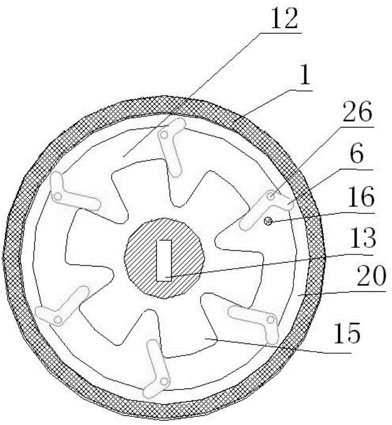
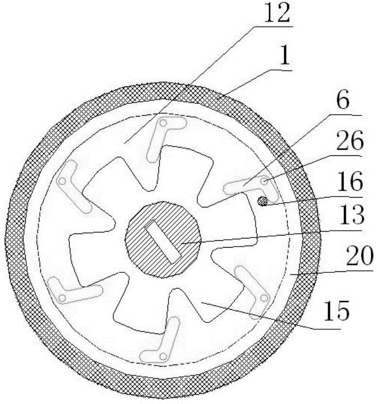
[0068] Such as figure 2 , image 3 , Figure 4 with Figure 5 As shown, the structure of the first embodiment of the device for ensuring that the transport carrier is not opened according to the present invention includes a locking mechanism and a locking detection mechanism. Wherein the locking mechanism comprises a lock core 13 arranged at the center of the cover body 12, a key 2 inserted into the lock core 13, a face plate 15 fixed outside the lock core 13, several locks connected to the cover body 12 by turning pins 26 The tongue 6 and the dead bolt limit pin 16 fixed on the cover body 12 . The barrel body 1 is provided with an annular locking groove 20 which cooperates with the locking tongue 6 . Dead bolt can be angular, also can be linear.

[0069] A through hole is provided in the cover body 12, and an outer pin 21 with the same length as the radius of the cover body is placed in the through hole, and an inner pin 22 and a spring for cooperating with the outer pi...

example 3

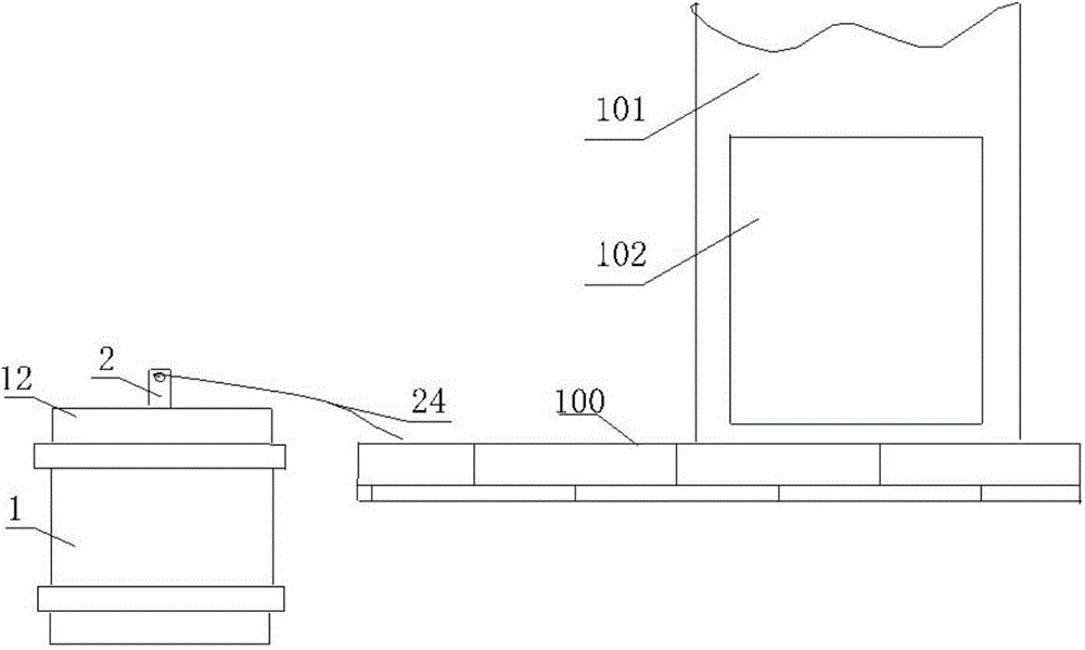
[0074] Such as Figure 7 As shown, in this embodiment, the key 2 is fixed with a handle 25 whose size is larger than the size of the entrance 102 of the delivery channel. The length of the handle 25 can be greater than the size of any direction of the entrance 102; The inlet 102 has a dimension that determines the direction. For example, entry 102 is as follows figure 1 Rectangular as shown, the length of the handle 25 only needs to be greater than the width of the inlet 102 . Other structures of this embodiment are the same as those of Embodiment 2 and will not be repeated here.


PUM


Abstract

The invention relates to the field of pneumatic pipeline transmission. A transmission carrier cover closure ensuring method includes 1, arranging a locking mechanism locking a transmission carrier cover and barrel on the transmission carrier; 2, arranging a locking detection mechanism on the transmission carrier; 3, utilizing the locking detection mechanism to detect whether the cover and barrel of the transmission carrier are locked through the locking mechanism or not, if not, locking the cover and barrel of the transmission carrier, and passing the transmission carrier on the condition of locking ensuring. A transmission carrier cover closure ensuring device comprises the locking mechanism arranged on the cover or barrel of the transmission carrier and the locking detection mechanism used for detecting the locking mechanism locks or not. By the aid of the method and device, the safety and reliability of the locking of the cover and barrel of the transmission carrier can be ensured, the transmitting efficiency is improved, and the privacy is optimized.

Description

[0001] This application is a divisional application of the invention patent application with the filing date of May 31, 2007 and the application number of 2007102007414. technical field [0002] The invention relates to the field of pneumatic pipeline transmission, in particular to a device and method for ensuring that the transmission carrier does not open the cover. Background technique [0003] Pneumatic pipeline conveying system can be used in all walks of life, such as hospitals, banks, factories, office buildings, shopping malls, restaurants and other places where items need to be conveyed. The pneumatic pipeline transmission system connects various departments, and items can be efficiently transmitted between any two transceiver stations, which can save people from running around, save a lot of time, and greatly improve work efficiency. However, the conveyor as a transmission carrier often causes the item to fall out of the conveyor because its cover is not locked, ca...

Claims


Application Information

Patent Timeline
Patent Type & Authority Applications(China)
IPC IPC(8): B65G51/04B65G51/36E05B41/00E05B19/22
Inventor 陆洪瑞
Owner BEIJING RINRONG TECH
Learn More