
Intelligent rotary track change control system and method

A technology for controlling the system and direction of rotation, applied to elevators, elevators in buildings, transportation and packaging, etc., can solve the problems of prolonging the construction period, increasing costs, and large construction plane positions, and achieve the effect of preventing accidents caused by over-rotation

Active Publication Date: 2017-03-15
CHINA CONSTR THIRD ENG BUREAU GRP CO LTD
View PDF18 Cites 2 Cited by
  • Summary
  • Abstract
  • Description
  • Claims
  • Application Information

AI Technical Summary

Problems solved by technology

[0002] In the construction of super high-rise buildings, in order to ensure sufficient vertical transportation capacity, it is necessary to equip multiple construction elevators, which not only occupies a large construction plane position, but also the construction of the exterior walls and related processes of the corresponding parts need to be carried out after the elevators are removed. , making the construction site process management complex and prolonging the construction period
In addition, in the existing construction elevators, there is basically no control system, and more rely on the driver's own judgment and manual rough arrangement, etc., which seriously affects the efficient performance of its performance, consumes resources and increases costs

Method used


Image

  • Intelligent rotary track change control system and method
  • Intelligent rotary track change control system and method
  • Intelligent rotary track change control system and method

Examples


Embodiment approach

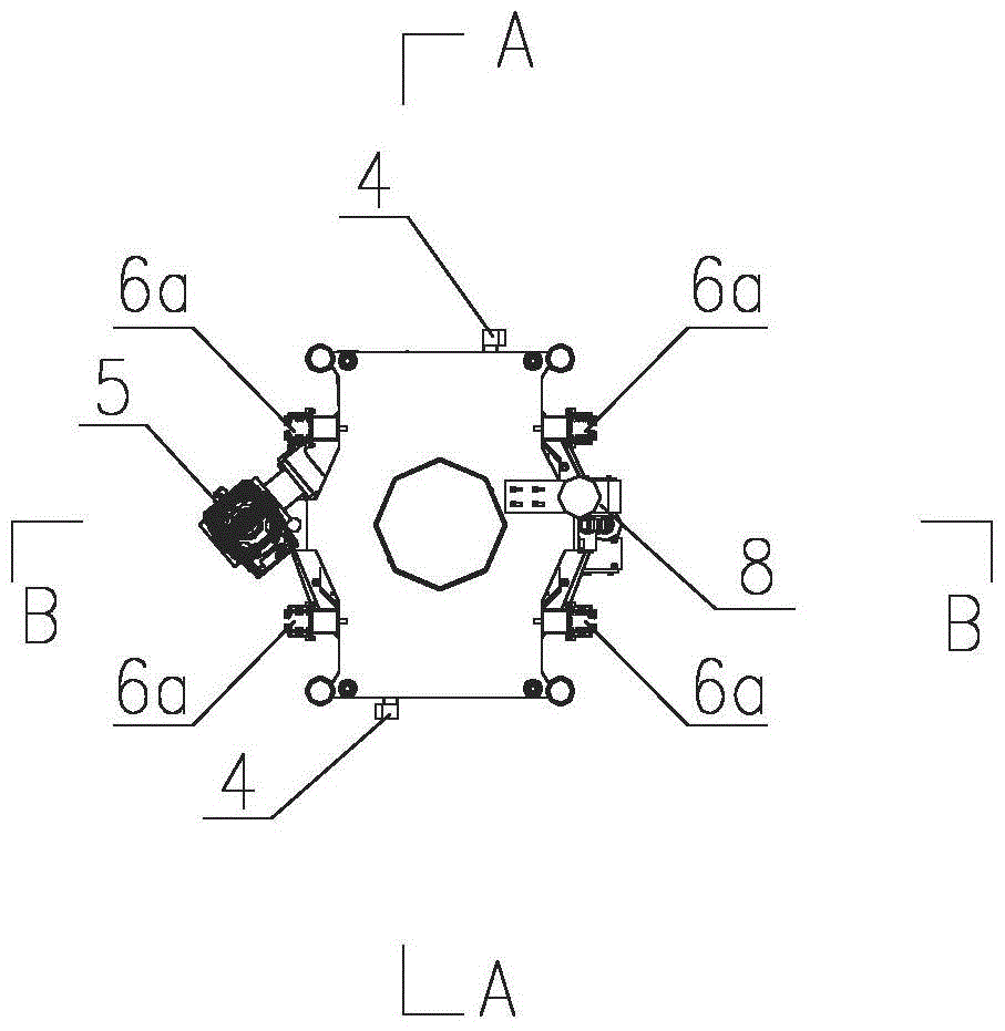
[0045] A method for implementing a rotary rail changing device, comprising the following steps:

[0046] S1. Install and fix the rotary rail changing device at the position where the track needs to be changed, turn on the power supply, and complete the mechanical and electrical debugging;

[0047] S2. When the ladder cage running along the track needs to change the track, it runs to the rotating frame and is connected to it for fixation;

[0048] S3. Unlock the rotating frame body and the fixed frame body (in this embodiment, the latch is driven to pull out the latch);

[0049] S4. The ladder cage rotates 180 degrees around the rotation axis together with the rotating frame body (in this embodiment, the rotating drive mechanism drives the bearing to drive the rotating frame body to rotate, the angle sensor is used to control the rotation angle, and the power supply device is used to ensure continuous power during the rotation process, intelligent And accurately realize the do...


PUM


Abstract

The invention provides an intelligent rotary rail exchanging control system. The control system comprises a sensor group, a rotary control unit and a rotary driving mechanism which are sequentially connected, and the rotary control unit is further connected with a user operation end used for judging the operation by a user; the sensor group is arranged on a rotary rail exchanging device, and comprises a rotary angle sensor, a rotary in-place sensor, an excessive-rotation preventing sensor and a rotary direction sensor, wherein the rotary angle sensor is used for calculating a rotary angle, the rotary in-place sensor is used for detecting whether the rotary location meets the requirements, the excessive-rotation preventing sensor is used for preventing an actual rotating angle from exceeding a preset angle and the rotary direction sensor is used for distinguishing a rotary rail exchanging direction; the rotary control unit is used for carrying out data analysis on data acquired by the sensor group, and transmitting a control command to the rotary driving mechanism. The automatic intelligent control that a construction lifter rotates on single guide rail frame by 180 degrees to change a rail can be realized; furthermore, the control system has the functions of automatically distinguishing the rotation direction and judging whether the rotation is in place, and preventing accidents caused by the excessive rotation, and further has a function of automatically resetting in an abnormal condition.

Description

technical field [0001] The invention belongs to the field of control systems of construction elevators, and in particular relates to an intelligent rotary rail change control system and method. Background technique [0002] In the construction of super high-rise buildings, in order to ensure sufficient vertical transportation capacity, it is necessary to equip multiple construction elevators, which not only occupies a large construction plane position, but also the construction of the exterior walls and related processes of the corresponding parts need to be carried out after the elevators are removed. , making the construction site process management complex and prolonging the construction period. In addition, in the existing construction elevators, there is basically no control system, and more rely on the driver's own judgment and manual rough arrangement, etc., which seriously affects the efficient performance of its performance, consumes resources and increases costs. ...

Claims


Application Information

Patent Timeline
Patent Type & Authority Patents(China)
IPC IPC(8): B66B9/16B66B1/06
CPCB66B1/2433B66B3/002B66B9/16B66B2201/30
Inventor 张琨王辉李迪叶贞伍勇军王开强周勇巴鑫夏劲松周杰刚
Owner CHINA CONSTR THIRD ENG BUREAU GRP CO LTD
Learn More