Multifunctional hydraulic support equipment

A hydraulic support and multi-functional technology, applied in mining equipment, mine roof support, earthwork drilling and mining, etc., can solve the problems of reduced mechanization efficiency, increased operation risk factor, and inability to adjust the space between the supports, so as to avoid the reduction of the working space , Reduce the empty top working space, reduce the effect of production cost

Inactive Publication Date: 2015-06-03
HUATING COAL GRP
View PDF6 Cites 8 Cited by
  • Summary
  • Abstract
  • Description
  • Claims
  • Application Information

AI Technical Summary

Problems solved by technology

[0002] At present, in the prior art of hydraulic support at the end, when the working surface is intermittently pressed, the top drops or the coal wall is displaced, resulting in repeated good and bad changes, because the width of the support top beam is fixed, the support cannot be adjusted. Therefore, it often causes coal leakage from the empty roof, clamping and deformation of supports, difficulty in moving, and inability to adjust between supports, etc., which has a great impact on the safe and normal production of coal mine working faces, resulting in reduced mechanization efficiency and excessive labor intensity of workers. , increased job risk factor, etc.
In addition, the existing terminal hydraulic support only has the characteristics of the terminal hydraulic support itself, and does not have the functions of the leading support hydraulic support and the end-tail hydraulic support, so it cannot play the role of "one support for multiple purposes".

Method used


Image

  • Multifunctional hydraulic support equipment
  • Multifunctional hydraulic support equipment
  • Multifunctional hydraulic support equipment

Examples


Embodiment 1

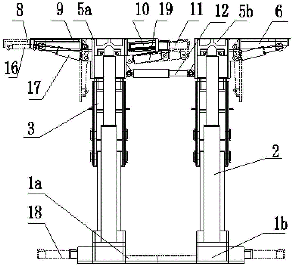
[0052] Such as Figure 5 shown as figure 1 It is a schematic diagram of the multifunctional hydraulic support device of the present invention when it is in the working state of the end hydraulic support.

[0053] When the multi-functional hydraulic support equipment is used as the end hydraulic support, on the one hand, it has the function of the end hydraulic support of the fully mechanized coal mine caving face in the traditional coal mine; on the other hand, it can be According to the changes in the displacement of each support on the working face, which lead to different degrees of empty roof and the change of the severity of roof breakage, timely adjustments are made, so as to achieve the functions of all-round support and frame adjustment, as follows.

[0054] 1) When the distance L between the end hydraulic support and the nose transition support 21 is too large, the top beam can be fully enclosed and supported by raising the flip beam 9 and extending the telescopic be...

Embodiment 2

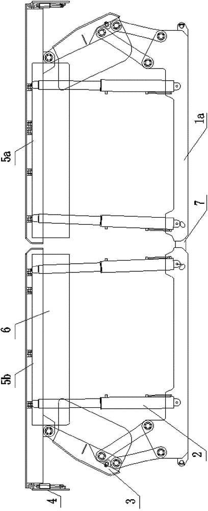
[0058] Such as Image 6 shown as Figure 4 Shown is a schematic diagram of the multifunctional hydraulic support device of the present invention in the working state of the end-to-tail hydraulic support of a large-inclination working face.

[0059] When the multi-functional hydraulic support equipment is used as the end-tail hydraulic support, when the width of the working face changes irregularly and the frame needs to be reduced or increased, its structure and function can be increased or increased by extending or shortening the top beam. The function of frame reduction can not only avoid the empty top operation on the working face, but also use the bottom adjustment beam to achieve the frame adjustment function between adjacent supports on the working face, the details are as follows.

[0060] 1) Since the front and rear groups of hydraulic supports of the multifunctional hydraulic support device of the present invention are structurally the same, on the same fully mechani...

Embodiment 3

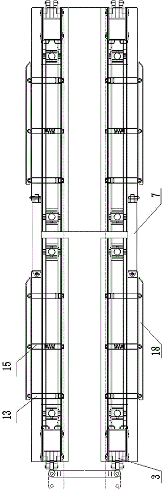
[0065] Such as Figure 7 As shown, it is a schematic diagram of the multifunctional hydraulic support device of the present invention in the working state of the advance support support.

[0066] When the two outlet roadways of the fully mechanized top-coal caving face in the coal mine need to be supported in advance due to incoming pressure, etc., the multifunctional hydraulic support device of the present invention can be used as the advance support support.

[0067] 1) When the width of the roadway becomes larger or comes under pressure, the upper end of the advance support bracket can be fully closed and supported by raising the overturning beam 9 and stretching the telescopic beam 8; on the contrary, falling back and retracting. And both sides of the lower end of the advance support support can reduce the displacement of the coal wall 23 by extending the bottom adjustment beam 18 and pushing the sleepers 20 etc., so as to ensure that the advance support support is not clamp...


PUM


Abstract

The invention discloses multifunctional hydraulic support equipment used for a fully-mechanized top coal caving face underground coal mine. The equipment consists of two groups of hydraulic supports and a pushing jack, wherein the two groups of hydraulic supports are arranged forwards and backwards and are of same structures, and the pushing jack is connected with the two groups of hydraulic supports; each group of hydraulic supports comprises two bases, four vertical posts, two top beams and a link mechanism respectively hinged with the corresponding base and the top beam; each group of hydraulic supports further comprises an overturning and telescoping mechanism and a bottom beam adjusting and telescoping mechanism, wherein the overturning and telescoping mechanisms are arranged at one sides of the top beams and are used for adjusting the supporting distances of the top beams according to the width of the fully-mechanized top coal caving face, and the bottom beam adjusting and telescoping mechanisms are arranged at one sides of the bases and are used for adjusting the distances between the bases and other supports. The equipment provided by the invention is simple in structure and convenient to use, 'one support having three functions' can be realized, the research and development expenditure and research and development time can be saved, the production cost can be reduced, and the proper adjustment can be carried out according to the change of the distance between face supports or the width of a roadway, therefore the universal support on the face and the roadway can be realized.

Description

technical field [0001] The invention relates to the field of hydraulic supports for fully mechanized mining working faces in coal mines, in particular to the field of fully mechanized caving coal caving working faces which are suitable for steeply inclined fully mechanized mining caving faces or are impacted and deformed by mine pressure, and the parameters of roadways and working faces change irregularly. hydraulic support equipment. Background technique [0002] At present, in the prior art of hydraulic support at the end, when the working surface is intermittently pressed, the top drops or the coal wall is displaced, resulting in repeated good and bad changes, because the width of the support top beam is fixed, the support cannot be adjusted. Therefore, it often causes coal leakage from the empty roof, clamping and deformation of supports, difficulty in moving, and inability to adjust between supports, etc., which has a great impact on the safe and normal production of co...

Claims


Application Information

Patent Timeline
Patent Type & Authority Applications(China)
IPC IPC(8): E21D23/04
CPCE21D23/04
Inventor 谢俊文卢熹仇安东上官科峰李慧关俊文杨世杰李汉汉貟彦章
Owner HUATING COAL GRP
Why Eureka
Try Eureka