Variable-direction transmission device

A transmission device and transmission joint technology, which is applied in the direction of transmission device parts, belts/chains/gears, mechanical equipment, etc., can solve the problems of limited application scope and achieve the effect of expanding the application scope

Inactive Publication Date: 2015-06-03
孟书芳
View PDF5 Cites 0 Cited by
  • Summary
  • Abstract
  • Description
  • Claims
  • Application Information

AI Technical Summary

Problems solved by technology

[0003] At present, most of the commonly used transmission devices

Method used


Image

  • Variable-direction transmission device
  • Variable-direction transmission device

Examples


Example Embodiment

[0013] The preferred embodiments of the present invention will be described in detail below with reference to the accompanying drawings, so that the advantages and features of the present invention can be more easily understood by those skilled in the art, and the protection scope of the present invention can be more clearly defined.

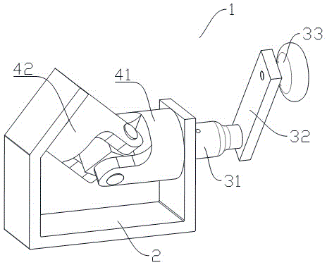
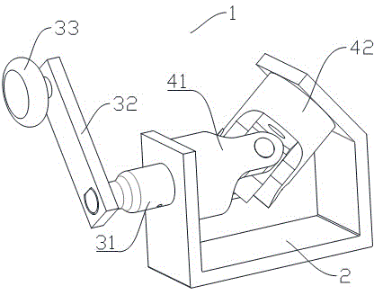
[0014] The invention provides a direction-changing transmission device capable of multi-angle transmission.

[0015] like figure 1 , figure 2 As shown, a direction-changing transmission device 1 includes a base 2, a rotating shaft 31 is arranged on the base 2, and one end of the rotating shaft 31 is fixedly connected to a control rod 32, The end is provided with a handle 33, the other end of the rotating shaft 31 is provided with a first transmission joint 41, a second transmission joint 42 is buckled on the first transmission joint 41, the first transmission joint 41 and the The second transmission joints 42 form an obtuse angle.

[0016] l...


PUM


Abstract

The invention discloses a variable-direction transmission device. The variable-direction transmission device comprises a base, a rotating shaft is arranged on the base, a control lever is fixedly connected to one end of the rotating shaft, a handle is arranged at the tail end of the control lever, a first transmission connector is arranged at the other end of the rotating shaft, and a second transmission connector is connectedly fastened onto the first transmission connector. The first transmission connector and the second transmission connector in movable connection through a connection rod are made of tungsten steel and form an obtuse angle. Due to the fact that the first transmission connector and the second transmission connector are arranged on a body of the variable-direction transmission device and movably connected through the connection rod, the requirement on angle variation can be better met while power transmission is guaranteed, and accordingly application range of the transmission device is greatly widened.

Description

technical field [0001] The present invention relates to a transmission device, more precisely, a direction changing transmission device. Background technique [0002] The transmission shaft is a rotating body with high speed and few bearings, so its dynamic balance is very important. Generally, the transmission shaft must undergo a dynamic balance test before leaving the factory and be adjusted on a balancing machine. [0003] At present, most of the commonly used transmission devices are linear transmission, and the scope of application is limited. Contents of the invention [0004] The present invention mainly solves the technical problems existing in the prior art, thereby providing a direction-changing transmission device capable of multi-angle transmission. [0005] Above-mentioned technical problem of the present invention is mainly solved by following technical scheme: [0006] A direction-changing transmission device, comprising a base, a rotating shaft is arran...

Claims


Application Information

Patent Timeline
IPC IPC(8): F16H57/00
CPCF16H57/0018
Inventor 孟书芳
Owner 孟书芳
Why Eureka
Try Eureka