
Eureka
For R&D, Eureka makes reading and utilizing patents & technical documents easy.
Eureka AIR
Designed for self-driven R&D workflows. Generate viable solutions, solve complex R&D challenges, empower your innovation with AI.

Eureka Materials
Designed for material experts only. Revolutionize your material R&D, from search, analyze, to developing new materials.

TechResearch
Generate reliable direction feasibility study reports for your R&D in just a few steps.

TechSeek
Discover and master advanced knowledge NOW. Basics, ideas, possibilities, all at once.

TechMind
As an expert in R&D Theories, TechMind can generates customized viable solutions instantly.

TechRisk
Analyze your overall solution with one click, know your potential R&D risks in advance.

TechMonitor
Get weekly tech updates, stay abreast of the latest tech innovations and key insights.
Photovoltaic water tank
A water tank and photovoltaic technology, applied in solar thermal power generation, heating devices, solar thermal devices, etc., can solve the problem that the water tank cannot produce hot water, etc., and achieve the effect of simple structure and cost saving
- Summary
- Abstract
- Description
- Claims
- Application Information
AI Technical Summary
Problems solved by technology
Method used
Image

Examples
Embodiment Construction
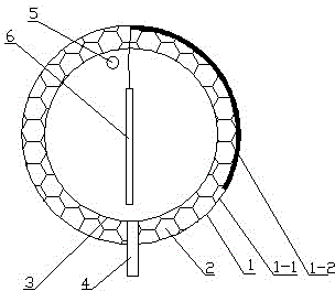
[0011] exist figure 1 Among them, the water tank casing 1 of the photovoltaic water tank is wrapped with a polyurethane insulation layer 2, and the polyurethane insulation layer 2 is provided with a stainless steel inner water tank 3, and the water inlet and outlet connection pipe 4 and the exhaust pipe 5 are connected with the inner water tank 3, and the water tank casing 1 is made of stainless steel. 1-1 is connected with the solar panel 1-2, the area of the solar panel 1-2 is one-third of the area of the water tank shell 1, the two pole output wires of the solar panel 1-2 are connected with the resistance heater 6, and the resistor The heater 6 is located in the inner water tank 3 .
PUM
 Abstract
Description
Claims
Application Information
 - R&D Engineer
- R&D Manager
- IP Professional
- Industry Leading Data Capabilities
- Powerful AI technology
- Patent DNA Extraction
Browse by: Latest US Patents, China's latest patents, Technical Efficacy Thesaurus, Application Domain, Technology Topic, Popular Technical Reports.
© 2024 PatSnap. All rights reserved.Legal|Privacy policy|Modern Slavery Act Transparency Statement|Sitemap|About US| Contact US: help@patsnap.com