
Rapid level gauge level-djusting structure

A leveling and leveling technology, applied in the field of leveling structures, can solve the problems of cumbersome initial adjustment process, errors affecting the measurement accuracy of the leveling instrument, etc., and achieve the effect of reducing requirements and facilitating disassembly and assembly.

Active Publication Date: 2015-06-03
NINGBO SUNNY SURVEYING & MAPPING TECH
View PDF5 Cites 11 Cited by
  • Summary
  • Abstract
  • Description
  • Claims
  • Application Information

AI Technical Summary

Problems solved by technology

[0003] An object of the present invention is to provide an easy-to-adjust leveling structure for solving the cumbersome initial adjustment process existing in the existing optical level adjustment structure, which can not only quickly and conveniently complete the leveling initial adjustment program, At the same time, it is beneficial to reduce the requirements for measuring personnel
[0004] Another object of the present invention is to solve the problem that the collimation axis of the telescope in the existing optical level adjustment structure is prone to large errors during level adjustment, thus affecting the measurement accuracy of the level, and to provide a quick level adjustment of the level Structure, which can make the telescope collimation axis of the leveling instrument have a higher levelness during work, and at the same time, the parallelism of the collimating axis is not easily affected by the human factors of the surveyor and the manufacturing and assembly accuracy of the leveling instrument

Method used


Image

  • Rapid level gauge level-djusting structure
  • Rapid level gauge level-djusting structure
  • Rapid level gauge level-djusting structure

Examples


Embodiment Construction

[0025] The present invention will be further described below in conjunction with the accompanying drawings and specific embodiments.

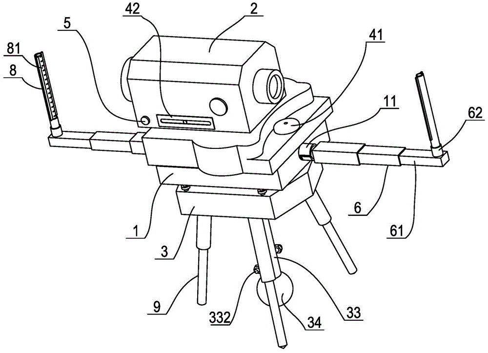
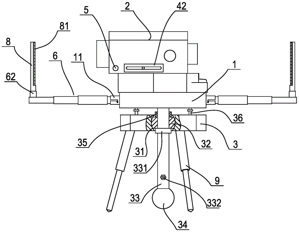
[0026] Such as figure 1 , figure 2 As shown, a quick leveling structure of a level includes a base 2, a level body 2 connected to the upper surface of the base by rotating a vertical axis perpendicular to the upper surface of the base, and a connecting bottom plate 3 arranged at the lower part of the base, A telescope for measuring is arranged in the level body, and a circular level 41 for monitoring the levelness of the initial adjustment program is arranged horizontally at the rear of the level body. The circular level is perpendicular to the collimating axis of the telescope. For the fine-tuning helix 5, a tube level 42 parallel to the collimation axis of the telescope is set on one side of the level body to monitor the parallelism during the fine-tuning procedure. In order to complete the initial adjustment procedure quickly and convenie...


PUM


Abstract

The invention discloses a rapid level gauge level-djusting structure. The structure comprises a base, a level gauge body and a connecting bottom plate, wherein a tubular level, a circular level and a tilting screw are arranged on the level gauge body; a spherical cavity is formed in the connecting bottom plate; two placing grooves tangent to the spherical cavity are formed in the upper surface of the connecting bottom plate; a disk-like floating block is arranged in and fit with the spherical cavity; an oscillating rod passes through the center of the floating block and is vertically connected to the lower surface of the base by a thread; a stop nut and a spacing ring are arranged on at the parts, at the upper and lower sides of the floating block, of the oscillating rod respectively; a control hammer is arranged at the lower end of the oscillating rod; a counterweight screw horizontally arranged from left to right is also arranged at the lower part of the oscillating rod; balancing weights are respectively connected at the left and right sides of the counterweight screw by threads; at least three adjusting screws are arranged on the edge of the upper surface of the connecting bottom plate; the upper ends of the adjusting screws abut against the upper surface of the base. The level gauge level-djusting structure can rapidly complete a levelness initial adjustment procedure and has higher levelness when a sight axis works.

Description

technical field [0001] The invention relates to a level, in particular to a leveling structure used for adjusting the collimation axis to a horizontal state when the level is measured. Background technique [0002] Leveling devices are mainly used to measure the height of a certain point or the height difference between two points in construction and other projects. Existing optical level measuring devices usually consist of a level and two leveling staffs. The level mainly includes a base connected to a tripod, a body rotatably connected to the base through a vertical shaft, and a The telescope, which is composed of objective lens, eyepiece, alignment lens and reticle, etc., is also equipped with a corresponding leveling structure on the body, so that the collimation axis of the telescope can be adjusted to a horizontal state during measurement. The leveling structure mainly includes a circular level set on the body to indicate whether the vertical axis is vertical, a tube...

Claims


Application Information

Patent Timeline
IPC IPC(8): G01C5/02
CPCG01C5/02G01C9/24G01C25/00
Inventor 蔡立高孙杰成聪
Owner NINGBO SUNNY SURVEYING & MAPPING TECH
Features
  • Generate Ideas
  • Intellectual Property
  • Life Sciences
  • Materials
  • Tech Scout
  • Unparalleled Data Quality
  • Higher Quality Content
  • 60% Fewer Hallucinations
Learn More